Setting-up the PM 1236-T Lathe

First of all, why a mobile base? For me it is primarily for access to those things behind the lathe: the electrical box, coolant system, stored spare parts, etc. Also, it is nice to be able to pull the machine away from the wall and adjacent machines to allow long stock to extend from the spindle bore. It was very nice to be able to easily roll the lathe away from the wall when I installed a taper attachment and the coolant and guard systems as well as my tool holding systems, and sometimes you just want to clean up back there. So for me, there are a lot of reasons for a mobile base. All of my equipment can be moved, even my mill, but none seem to be as touchy to movement as a lathe so I wanted a system that would allow me to move the lathe without needing to spend a bunch of time re-adjusting it. It seemed like a pay-me-know-or-pay-me-later situation; spend the time now putting together a system that will allow me to move the lathe around without needing to re-adjust or spend the time later re-adjusting, or at least checking the adjustment, every time I moved it. The mobile base that I put together has three components:

1.) Outriggers with casters
2.) Machine mounts
3.) Baseplate
 
First of all, why a mobile base?

I agree with this question. Once you get an offset part dialed in in the 4-jaw chuck, the lathe will walk itself across the room unless there is no way for it to do so.
The casters provide that way.
 
Mitch Alsup, I have not tried an offset part in a 4JC but the set-up has been rock solid with everything else I have tried over the last year.
 
Damn dude, back off. He bought a manual machine not a CNC for starters. It’s his thread, if you don’t like it you DON’T have to follow.
It appears that you failed to understand the humor.
The quality or usefulness of a machine tool is not dependent on accurate decal placement.
 
@P.Waller - your hijacking of this thread is over. Your attempt to recast your prior posts as humor falls dead flat with this membership. This is your first and final warning to keep your abrasive comments to yourself.


Sent from my iPhone using Tapatalk
 
1.) Outriggers with Casters

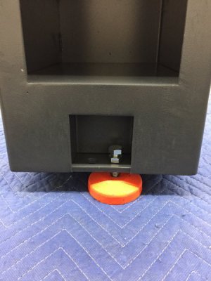
This is what comes with the lathe: a cast iron puck, a bolt and a nut.

801E27B7-56F6-48C9-AACC-DB614543C5E8.jpeg

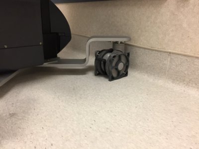
Here is a configuration that I considered from a piece of equipment at work

CB7D0224-486A-482E-A337-9D254B5DED57.jpeg

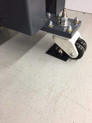
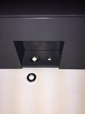
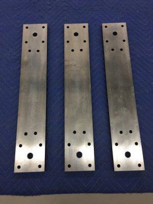
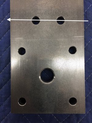
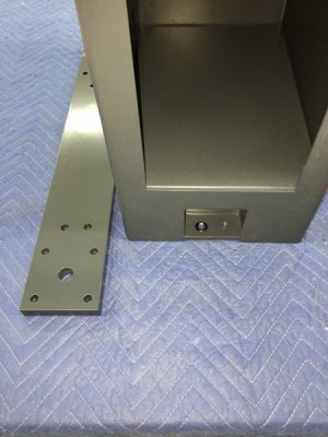
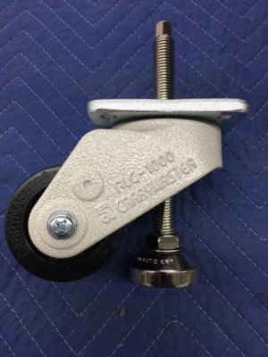
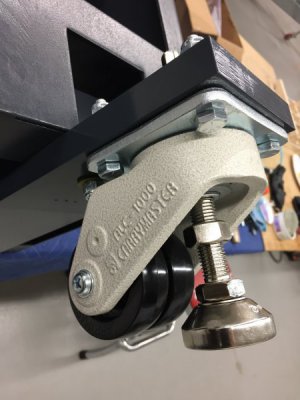
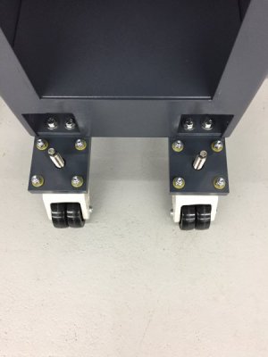
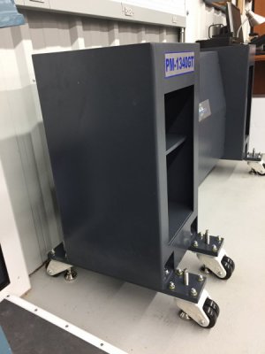
That arrangement was appealing because it lowered the CG of the cabinet but I wanted casters that I could adjust the leveling foot with a wrench rather than a plastic wheel that most of the casters have, in addition the bent arrangement of the outrigger would get in the way of the cabinet doors. I went with straight outriggers. I used three 1/2”x 4”x23” pieces of 1018 cold finish steel flat. The cabinet is 15” wide so this gave me a 4” x 4” area extending from the cabinet to attach the casters. All the holes are 3/8” except the larger hole for the M16 leveling foot which is 3/4”. The outriggers were then painted and attached to the base. The holes on the base are a different size and offset a bit so you have to take that into consideration when measuring. I used a spacer to account for the different diameters:

8401A5BE-026E-4D9D-B1B9-2A4E06ED02A2.jpeg. C885E79F-BCF8-4579-8153-A58D41C83B02.jpeg

D15283ED-D75D-4B39-BB2C-0EA9CC732385.jpeg. F604494D-B9B8-4E90-8B7D-CF0FDDF66692.jpeg

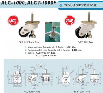
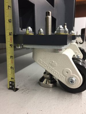
I used Carrymaster ALC1000 casters. The outriggers were attached to the cabinet and the casters attached to the outriggers using 3/8” x 1-3/4” bolts.

553C29CC-0FAF-4813-A9E8-68504B036DEC.jpeg. D2D62E34-6EDF-401E-826E-F38D5EC70670.jpeg

C8628D5F-1BC3-43DE-8046-45122D1F62BE.jpeg. BC68F4B6-7233-420D-AA1C-4301A44A1949.jpeg

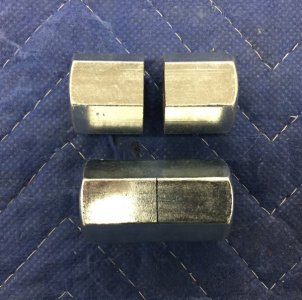
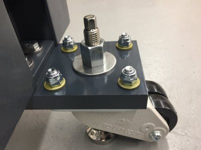
I used 2” fender washer and an M16 coupler nut that had been cut in half to act as a lock nut on the leveling foot.

3A623EB5-A09A-42DE-9861-9248C6FD9C16.jpeg. C576B9E7-3A5C-4AC8-A341-F6F9FA8F5F01.jpeg

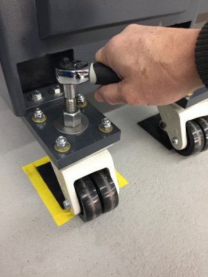
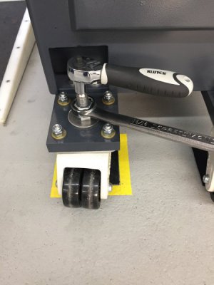
I am then able to make fine adjustments of the leveling foot with a small wrench and then secure the position with a larger wrench on the coupling nut.

50448409-20D8-4E53-B0D8-C8782DF65569.jpeg. 35355730-04D5-4414-B903-44D780A0BF4C.jpeg

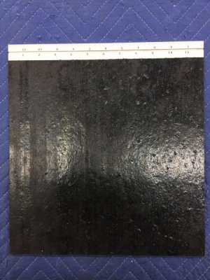
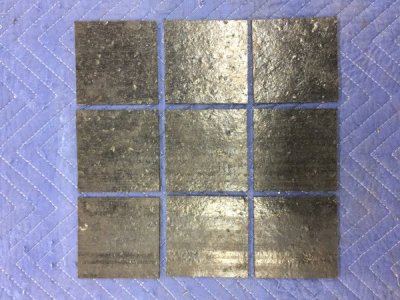
I added some equipment pads to help keep the lathe from walking but I think they are overkill. The machine is very solidly in position without them.

4D38FD78-ADA0-4A17-B1FF-3EF0B70AA98F.jpeg. E7AF17A3-6C56-4EB4-A75B-E2804DF8EF0D.jpeg

This added about 5” to the cabinet height. The PM puck-and-bolt is about 1-1/2” so there is a net gain of about 3-1/2” over the puck-and-bolt configuration.

D72A051A-4646-4FE0-B6D7-45776A3AEB93.jpeg

That’s it for the outriggers. Tomorrow I will try to do the equipment mounts and hopefully the day after the baseplate.
 
Back
Top