Sheetmetal dreams.

And to address your other comment -- yes, the stretching done to create the halves leaves the metal thin. The original pants were made from .050" material, the ones made for the DGA-8 started out as .063" thick material. If I had had that tooling for the halves I would have made the initial blank out of maybe three pieces and made sure most of the metal that needed to be in the cavity was in there from the start. That way there would be little stretching and thinning, just enough to finish the shape. Or I would have used the tooling to flow-form the part and not use the water at all. In developing the process for water forming they busted the aluminum on more than one attempt. They finally backed off on the pressure and did more anneal cycles to get acceptable parts.
 
now there's another
I made a couple of TuckPuck style PVC tools but I haven't really used them. I only tested that I could make a tuck and close the tuck using that tool. It's like having a small hollowed out stump that fits in a tool box.

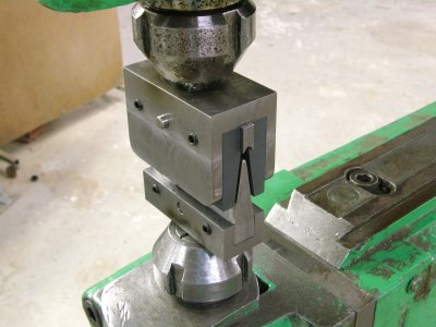
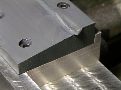
I had to make some tucks to shrink the edge of the intersection fairings on the Howard. I made a tucking die set for the rivet squeeze and flattened the tucks by trapping them with a backer plate and two small C-clamps -- again using the rivet squeeze with either a steel or PVC flat die. Worked pretty well and I was able to control the results because I wasn't using a hammer. :)


View attachment 384180


View attachment 384181

View attachment 384182
Now there is another great idea, using the rivet squeeze. I don't have one of that type but I have a big ol pneumatic Chicago squeeze that I've never used. Partially because I've not done a single solid rivet since aircraft school in '83, but also because I got no sets with it. But with the lathe I can make whatever I want. What did your tuck sets look like for the squeeze? more just V shaped?

I'm curious how big you make your tuckpuck and how deep you made the dish? It would be nice to have kind of a starter puck for the arbor press. I am just guessing at the dimensions off his website. My dad was friends with the butcher up in Yosemite Park and got his old 4'x4'x2" UHMW cutting block when they swapped it out in '85. So I've been cutting that thing up and making stuff out of the scraps for decades. Wonderful stuff to machine and wears better than steel.
 
And to address your other comment -- yes, the stretching done to create the halves leaves the metal thin. The original pants were made from .050" material, the ones made for the DGA-8 started out as .063" thick material. If I had had that tooling for the halves I would have made the initial blank out of maybe three pieces and made sure most of the metal that needed to be in the cavity was in there from the start. That way there would be little stretching and thinning, just enough to finish the shape. Or I would have used the tooling to flow-form the part and not use the water at all. In developing the process for water forming they busted the aluminum on more than one attempt. They finally backed off on the pressure and did more anneal cycles to get acceptable parts.
This is what I've learning from my cake pan. There are always tradeoffs and there is no free lunch. You might find an easier way in theory but like in bubble forming are you really saving that much time? I'm glad folks try out these ideas and hopefully post their findings so you don't have to re invent the wheel. Or can avoid the known pitfalls. I can see if you don't like doing this kind of hand forming but for me it's addicting. But it always leads me into wanting that "if I only had THIS, I could do it right" syndrome.
 
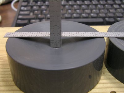
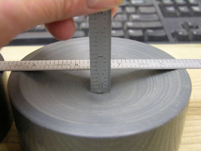
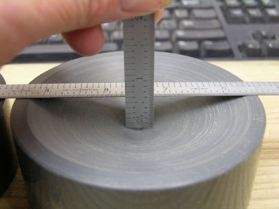
The knock-off TuckPucks are 4" diameter, there are two with different depths;


DSCN5018as.JPG
DSCN5019as.JPG

The scale doesn't reach to the bottom but anything close to this should work.

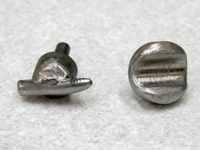
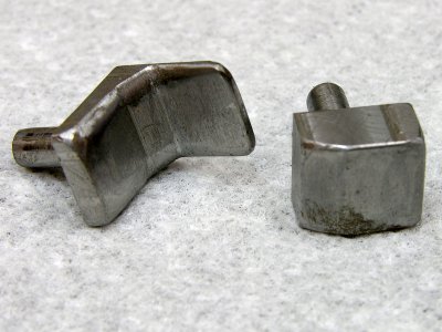
My tucking dies are pretty crude and they don't self-align. They got the job done a with minimal build effort. The male is an old AN3 bolt.

DSCN5020asc.JPG

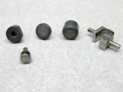
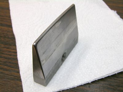
Here are some other dies I made;

DSCN5021as.JPG

DSCN5022asc.JPG
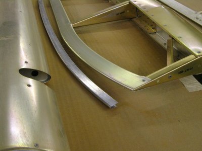
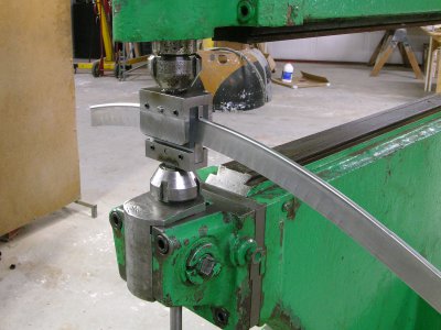
These edge bevel dies were made for the Howard intersection fairings which had some edges done this way. I also made some similar dies for the Pullmax but I eneded up using these most of the time.........
 

Attachments

  • DSCN5019as.JPG
    DSCN5019as.JPG
    165 KB · Views: 3
Thanks. So the shallower puck looks like it was used more, yes? What do you drive into the puck? Yours and the TuckPuck look like they are more cone shaped than round like done with a ball turner. Is that on purpose so it more matches a rounded point driver?

I like the tucking dies. Are the top left 3 in photo 4 made of plastic? The one with the hole is for dimpling for flush rivets?

Shoulda known a guy like you with all the nice toys has a Pullmax :) Did you use the step die on the rivet set because you could work more slowly/deliberately? I love the idea of a reciprocating machine like the Pullmax because it seems so versatile. You can shrink,stretch,planish and form. I almost think rather than make a planisher I’d rather make a recip like a Pullmax. They sell shrinker dies for planisher but I’m skeptical because the only machine I’m aware of that you can totally control your stroke is a recip. All planishers and hammers don’t have that ability, the stroke is not controlled. You can control the pressure but ultimately the work is the stop where the recip is controlled by the eccentric. But it’s just a concept as I’ve never even used a planisher.
 
The Pullmax was a long time search. Took me about ten years to find one local to me. I almost bought a 4000# Trumpf CN700 but it was really too big and heavy for my needs and they couldn't power it up to demonstrate it was fully functional. The P-3 I have is about ideal for a guy like me who does aluminum 99% of the time. I have a special project in mind for it, maybe I should show it here even though it's far from done -- there's only a rather disappointing first try to report on (but making the tooling was an interesting machining challenge).

The recip machines like a Pullmax are fixed stroke so planishing is not their best trait. If you are planishing a shaped panel where the thickness varies even a few thousands the thicker areas will tend to stretch a little while the thinner areas may smooth well without any noticeable stretch. The stroke should not be controlled when planishing, only the pressure should be controlled. I will get some thumbnail shrinking dies for mine at some point but the knock on the Pullmax and similar machines is the setup for the thumbnail dies has to be re-done every time you put them in the machine. A dedicated shrinking machine is better because the dies can stay in the machine.

Yep, those three dies are PVC. The middle one is all PVC, including the shank -- I keep waiting for it to break.... The one with the hole is a 'crutch' tool made because some of my riveting on the wheel pants proved to be difficult in a few spots. The hole is for the stem of the rivet and the need for this crutch is to re-seat the rivet after a very light squeeze to bring all the panels back into contact and to get the head down flush before a full squeeze. Soft rivets don't seem to have much, if any, ability to draw the parts together as you set them or at least that's my story.

I haven't used either puck except to test them briefly.
 
Last edited:
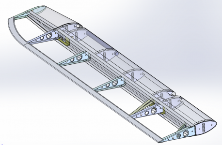
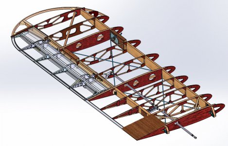
Here are a few photos of my dream (or nightmare) Pullmax project.


DSCN4560as.jpg
This is the goal -- Make a trailing edge part as beautiful as the stretch formed ones from the Christen Eagle Kits. Shown here with my very first test piece.

TE Tool Holders2.JPG
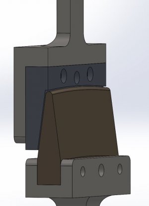
The Solidworks models of the dies.

DSCN4564as.jpg
The machined male die #1. Not enough curve in the part......

DSCN4576as.jpg
Installed in the Pullmax, gen2 female. The gen1 female was all PVC and it did not hold up well. See below;

DSCN4563as.jpg
This needs better plastic or a steel insert!

DSCN4574acs.jpg
This is as far as I have gotten using just these dies. The part is trying to shrink along the edge but it's not really happening.

I pre-shrunk a blank which might work (and be a bit ugly) but the alignment of the top and bottom dies seems to be causing the part to distort out of plane. I think the bottom die needs to float a little so it does not impart a bias to the blank. I'll try that when the shop move is done and I get some time........ This is not an easy thing to pull off and I may end up making a stretch forming fixture if the Pullmax can't be persuaded to make this part.

The ultimate destination for these parts is my Pitts S-1 project.........

1635972449273.png
LWR Wing Overall 3-14-2018.JPG
 
Last edited:
Some pretty sweet sheet metal work going on there, guys. Very impressive :encourage:

-frank
 
......Shoulda known a guy like you with all the nice toys has a Pullmax :) Did you use the step die on the rivet set because you could work more slowly/deliberately?....
Sorry I missed this question. The tooling for the Pullmax was offset forward to gain some clearance for the part from the machine. It wasn't enough and trying the use it required my wife's help to raise and lower the upper die when I was ready. And still I couldn't hold the part's position well enough to do the entire edge cleanly. The rivet squeeze was much easier to deal with in terms of part clearance and keeping the die's reference surface engaged with the part. But man, when you got it right with the Pullmax it was a great result.........
 
Besides everything else the challenge of holding large work while forming is like doing target shooting from the back of a galloping horse. Trying to figure out how to make something or how something was made is usually a fun puzzle. Seeing how that trailing edge is remarkable. I can only think it could be done by stretching so you don’t end up with those wrinkles from the edges trying to gather. That material has to go somewhere. Have you seen the rig they use to do that?
 
Back
Top