Sheetmetal dreams.

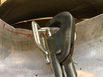
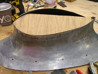
I designed some clamps in Solidworks to help position the parts during the tack weld process. I tried 3/32" Clecos with two plates to capture the edges but the gap was way too large to deal with. The clamps I made use .015" spring steel (something I had on hand) which makes for a fairly tight joint. The problem is that when the tacks shrink they tend to trap the clamp requiring I either tap the clamps away from the tack or remove them by disassembling them.

Brilliant idea for clamps!!!!

I will have to save those photos when I'm back on my home PC.
......but it is meant as the sincerest form of flattery!

Thanks for sharing all this info!
-brino
 
Here's the drawing I used to make them. Somewhat incomplete since it was for my own use but the materials are aluminum for everything except for the spring steel joining tabs.
 

Attachments

  • Weld Clamp.pdf
    12.5 KB · Views: 7
very cool idea on the clamps! I could see these as a very useful, necessary actually, for this kind of weldment. I LOVE the idea of the cleco's to act as the temp pivot. genius.

I don't get how you ended up with the gap at the end. The guys I've seen do this kind of thing make them long/overlap, trim the first, then use the first to mark to trim the other. Is that how you did it and it's still a Pope's hat? If so maybe some planishing of the welds as you go to stretch to fit?
But I guess that might mess up your fit off the bulkhead you were installing.

Sorry, I'm obviously no expert and shouldn't be spouting off, but just thinkin' out loud I guess.
 
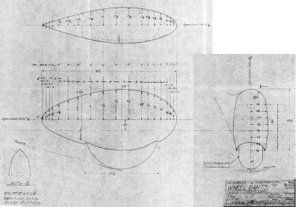
Here's the factory drawing;

D-13-10, Condensed.JPG

I had no original part to reference so it was the water-blown wheel pant halves and this drawing. In the lower left corner you can see the profile and the note about the profile change starting at section 11. I assumed this was to make a gentle transition from to 'round' tangent shape the two halves naturally create to a thinner trailing edge at the aft end of the pant. Basically I faked it as best I could since the 3D Solidworks model the tooling was made from did not really include this feature.

The gap didn't really have anything to do with the change of profile. The parts I was working with still had the flange on them from the forming process and the blanks were pretty flat. Below is a different part for a WACO cabin biplane. The one for the Howard had a 1"R blend between the flange and the part.

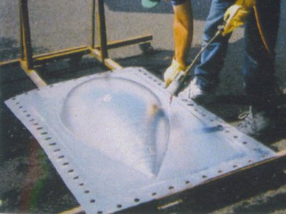
Forming Process.JPG

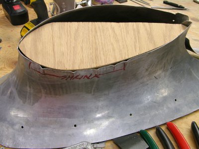
I used a height gauge with a scribe to define the trim line for the two halves. I then cut off the flange and the blending radius and I also began to create the hole for the gear leg and tire (starting way small). Those two things caused the cut line to go out of plane a little, about 5/16" per side. But there was no effort involved to bringing the ends back together and my fixturing had references so I could make sure the finished joint stayed centered and in-plane.

DSCN3408s.jpg

That's how I did it but there are 100 ways to do most anything like this........
 
there are 100 ways to do most anything like this........
I hear that! Thanks for the explanation. All of that is way different than the pieces I've seen done. #1 being way bigger and being supplied with the part already formed. Where the guys like Covel do the forming from scratch. When you say "water blown" I picture hi pressure water blowing the part into a form. This reminds me of Jere Kirkpatrick "flow forming" with an impact gun with a nylon hammer into a form.
 
Yes, the owner is a very creative guy and he came up with a variation on the hydroforming method that uses water pressure instead of a bag of oil or rubber as the pressurized fluid. Originally he was thinking to use a small pressure washer pump to supply the force but with all that surface area you really don't need or want that much pressure. I recall they ended up using city water pressure. The big negative of this method is the size and weight of the tooling coupled with having to anneal multiple times to get the part fully formed. You can see in the photo how many fasteners were used to hold the lid down, And the lid was like 1-1/4" thick steel which required a forklift to lift it off the mold. It's not a practical technique IMHO.

The parts I had were the only four halves in existence, the tooling having been damaged beyond use while they developed the process. They were all slightly different and I don't think any of them were fully formed into the cavity. What you really need is a buck for use as a way to confirm you have a fully formed part but that was not done AFAIK.

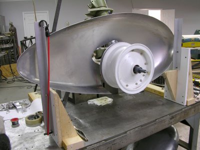
I had no room to spare inside the pant so I had to keep the pant aligned with and centered on the tire. The way I did it was the best way I came up with to accomplish this.
 
. I recall they ended up using city water pressure.
WOW, I would have bet the pressure washer wouldn’t have been enough but I wasn’t thinking of it being in a sealed setup more like flow forming with the pressure washer into the form. that fixture sounded like literally a ton of work.
 
Thanks for the link. I’ve rented from them before and it’s a wonderful set up.

Now keeping in mind I’m just a noob hack I would think any kind of forming like this would really stretch and thin the metal where the old tuck and gather method actually end up with thicker metal overall as you’re just working the edges instead of blowing a big ol bubble.

I have to say I’m enjoying my reforming my cake pan and would recommend it as a way to do some metal shaping to put vid knowledge and theories to practical use. Of course it leads me down the rabbit hole of more tools and fixtures. The tool is really an addition to my arbor press that is turning into my tool of choice for metal forming. It’s called the Tuck Puck:
 
I made a couple of TuckPuck style PVC tools but I haven't really used them. I only tested that I could make a tuck and close the tuck using that tool. It's like having a small hollowed out stump that fits in a tool box.

I had to make some tucks to shrink the edge of the intersection fairings on the Howard. I made a tucking die set for the rivet squeeze and flattened the tucks by trapping them with a backer plate and two small C-clamps -- again using the rivet squeeze with either a steel or PVC flat die. Worked pretty well and I was able to control the results because I wasn't using a hammer. :)


DSCN4815a.JPG


DSCN4813a.JPG

DSCN4817a.JPG
 
Back
Top