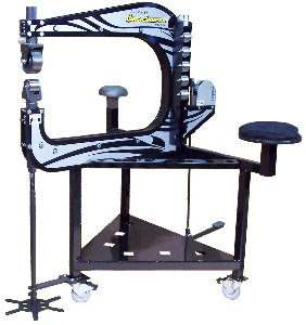
Sheetmetal dreams.

Yeah, metal is clay but it's clay with an attitude.........
LOL, just got to be more stubborn than it. It does help as always to have the right tools because there is almost always an easier way. My problem is I usually come to it after the job is over or close to done. I can see the corking tools are going to be key and I have a bunch of UHMW scraps that have been waiting for this.

I‘ll check out that vid.

If not for HF I’d have very little. The hammer is also HF and I modded/ground and polished it and I like it a lot. But not ever having a real SnapOn or “real” body hammers what do I know? I have two of the Eastman plastic hammers and they came ready to use unlike the HF. The HF come to points on both ends, WTH? But the Eastman say they are UHMW and wear good but are way light, don’t feel like UHMW at all. Maybe nylon? dunno.
 
Yes, the carbon burns off at about 750°F which is the right temperature for softening aluminum. You can also use a black Sharpie pen since the pigment in the ink is carbon. When you're burning off the carbon you should have a neutral flame as opposed to a carburizing flame. For small stuff you can use a MAPP gas torch.
 
Besides being behind on execution of projects I was not sold on the way typical T-dollies are made. Jere Kirkpatrick to the rescue. He posted this dollie reciever a while back and while an excellent idea for being able to work the dollie in any direction without it wandering, I think I would rather make it mount directly to my workstation and not have to tie up a vise.

 
I wouldn't mount anything on my EW frame that required a hammer to operate but I have the luxury of space. There are things in my junk collection, shapes, that I want to make into dollies and I have a big anvil with a socket for stakes but so far I have done nothing to make that happen. It seems these projects are driven by need and so far there has been no need. I did buy some cheap (junk?) dollies at HF but I recall the shanks being too small for the socket in my anvil. I could see using the HF dollies for aluminum but I question how long they would last bashing steel.
 
I wouldn't mount anything on my EW frame that required a hammer to operate
Why? when I said workstation I wasn’t being very specific but I was thinking the portable bench that the woodworker vise was on. Because I don’t have the luxury of space everything is a workstation.

I never saw the HF dollies, but the ones in the body hammer kit seem to be really tough. I used them when doing the 22ga galvanized and there’s not a ding in them. Just like the hammer. It’s kept it’s polish remarkably well. Of course they all need reworking and polishing but even expensive hammers and dollies need that.

But that got me thinking, maybe beating constantly on that bench isn’t the best idea because my expensive powder coat head is in that.
 
I don't like the thought of adding impact loads to the bearing under the spine of the EW. To me that bearing is marginal capacity wise anyway. It has not been a problem in all these years but I know someday it will begin to fail.

I figured, wrongly, that you were making your EW into a sheet metal workstation. Sorry I jumped to that conclusion. As you said, everything is a workstation when space is at a premium. I guess having vises on wheels is OK if you aren't going crazy with how they'll be used but it is opposite of my setup where my big vises and the anvil are on a very heavy steel bench that doesn't move without great effort.

Here's the dolly HF carried;

https://hfreviews.com/item.php?id=3140
 
Last edited:
it was easy to make that assumption because of the beader and shrinker/stretcher I bodged on to my EW. That is a good consideration. The Ron Fournier station has hammer use on it but they are on sub frames with feet under the sub frame so I would think that would isolate the EW bearings. But in my case that would defeat the purpose making the whole thing take up too much real estate.

1635701771872.jpeg
 
One more little contribution on the wheel pant subject since we all like to make tools to solve problems -- again from the original post on the Biplane Forum;

I designed some clamps in Solidworks to help position the parts during the tack weld process. I tried 3/32" Clecos with two plates to capture the edges but the gap was way too large to deal with. The clamps I made use .015" spring steel (something I had on hand) which makes for a fairly tight joint. The problem is that when the tacks shrink they tend to trap the clamp requiring I either tap the clamps away from the tack or remove them by disassembling them.
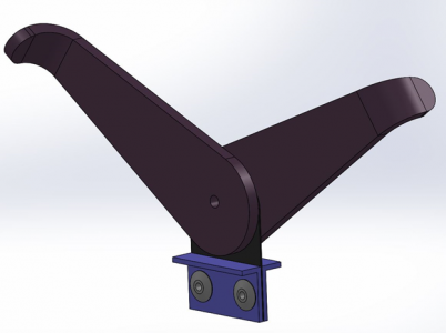
1635869512985.png
The clamps are held together with clecos to make disassembly easier. Disassembling a clamp is a small PITA but I think it's worth it because I can get good alignment between parts. The other advantage of these clamps is being able to align the edges on a large portion of the mating parts to confirm you like what you see before you start tack welding.
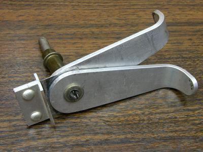
1635870786338.png

The two arms have an eccentric geometry that provides the clamping action. I made these without CNC so no two are exactly alike. I was wishing for a CNC machine while I was building these! Instead I used the disk sander and did it by hand. I tweaked one of the clamps for use at the nose end of the pant where the curves are fairly tight and the straight clamps don't work as well.
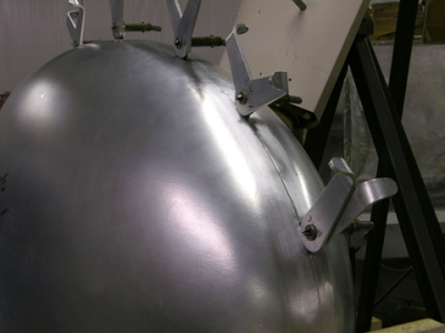
1635869602011.png

Pretty happy with the alignment these clamps provide.
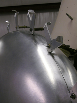
1635869685323.png

The gap behind the first clamp is about .025". It will close up as the tacks are placed -- welds always shrink and any gaps between parts will also shrink. You can see some marks made by the clamps on the edges to be welded. These will be consumed by the welds since they are only 1/8" wide.
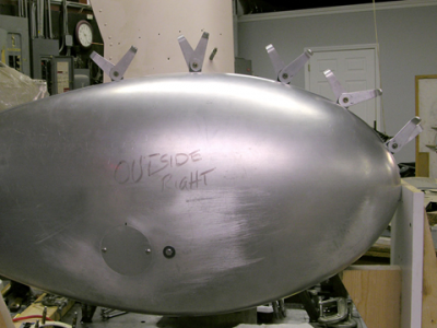

1635869724331.png

Side view with all five clamps in place.
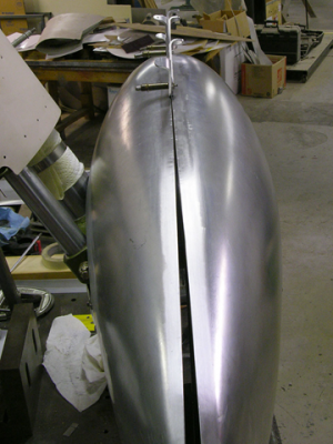
1635869764572.png

The gap here will close during tack welding. It takes very light pressure to close this gap and I should be able to get the clamps out before it's too late.

The aft 1/3 of the length of the pant transitions from the two halves being tangent at the weld to a sort of 'Pope Hat' shape. This will be tricky to weld while retaining the profile's overall shape. I'll have to resort to some sculpting of the welds and I'm not sure exactly how it will all work. I wonder how they did this back in the day? I suspect the joint between parts was not in the center on the aft end and they made a third piece for this area with the weld joints more along the sides. Anyway, I'll do it this way until it proves to be impossible.....
 
Back
Top