SW2 Analog control selection

mrbreezeet1

Active User
Registered
Joined
Mar 14, 2013
Messages
736
Did I do something wrong?
I went to reply to my post I started the other day and it is gone. I would have thought I would have gotten a PM if I had done something wrong.

I wanted to ask if the SW2 Analog control selection mattered. There is looks like an I or a V
 
With what little information you have given for analog input "I" would indicate the input was a amperage signal as in 4-20 ma. The "V" would indicate voltage input signal as in 0-5v or 0-10v etc. HTH. Good luck.
 
With what little information you have given for analog input "I" would indicate the input was a amperage signal as in 4-20 ma. The "V" would indicate voltage input signal as in 0-5v or 0-10v etc. HTH. Good luck.

Thanks, Sorry, My post Original disappeared , this is a Teco VFD JNEVS series, 101 H=1 110 volt input.

Seems I had to set switch "SW2 Analog control selection" to the other setting from factory setting (Not sure I or V now) for the Pot to work. If not, I was only getting about 10HZ change over the full range of the setting.


Let me ask, should a External control Potentiometer increase HZ turned to the right, like you would turn up the volume on a Radio, Or does it increase turning to the left?
Mine is to the left and would like to have it increase to the right,
I thought "Swap #9 and #11, but if I do that I get an Error code, equating to 0.00 HZ.
Also the Pot seems very "Touchy" esp. near the higher range.
I fooled around with the Pot. Trim gain setting, but it did not help the "Touchy" part.
My Min/Max Hz is set to 5HX min/90 HZ max right now.
Thanks,
Tony
[h=3][/h]
 
I saw your other post, and even replied to it. Strange things are happening around here lately :dunno:

I used the factory settings which I think uses the common lead, it was you option #1 in that other thread.

I think the speed/freq should increase as you turn the pot to the right, just reverse the two outside leads to change the direction.

What kind of pot did you use? Size? New or used?

My personal feeling is that the minimum HZ setting should be about 30, and max at 90.
 
Do you have a linear taper potentiometer? The typical pots you pick up at Radio Shack etc are "audio taper" rather than the "linear taper". If you use an audio taper pot you will not get smooth control.
http://en.wikipedia.org/wiki/Potentiometer


I saw your other post, and even replied to it. Strange things are happening around here lately :dunno:

I used the factory settings which I think uses the common lead, it was you option #1 in that other thread.

I think the speed/freq should increase as you turn the pot to the right, just reverse the two outside leads to change the direction.

What kind of pot did you use? Size? New or used?

My personal feeling is that the minimum HZ setting should be about 30, and max at 90.

Yeah, it was funny, when I refreshed the page that was already open, I got some cartoon figure in a "Test post" saying "Nelson You Suck"


OK, Yeah, NPN was the one that uses #8 common. Picture is attached below.
I will fool with it more tonight. I thought when I reversed the outside leads, That is when I got the error, relating to 0 HZ.
reason I wanted it Low, (HZ) was it's a wood lathe, I thought l could "Power brush" a finish on at the low speed.
I would only run it at the low HZ for a short while.
Yeah, it's a Radio Shack Pot,but I thought I had read that it was the correct type. Number is 271-1715. It is a new one.
said it is a 10 K linear taper. Unless there is something wrong with it.
I don't know?
I have read posts where other people have used this same part.
Again, I do not know for sure.
http://www.radioshack.com/product/index.jsp?productId=2062354

Parameter F06 = 000 Control method is as follows.JPG
 
Well that looks like the correct type of potentiometer but you can check it with an ohm meter if you have one. Typically the wiper is the center lead. If you hook one end lead to one wire of the ohm meter and the other wire of the ohm meter to the center lead of the pot you should see a smooth change as you turn the pot from 0 ohms to 10K ohms. Swap the wire to the other end lead of the pot and you should see the same thing only backwards. With the pot adjusted at the center is should read about 5K ohms from either end lead to the center. You should also read 10K ohms by hooking up the ohm meter wires to the two end leads (one wire to each). The parts from Radio Shack typically aren't the highest quality (and I am being kind). On a project I worked on 5 out of 8 op amps I purchased from Radio Shack were DOA. I would not be surprised by a mislabeled part from RS.

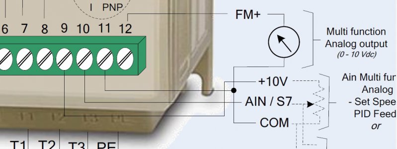
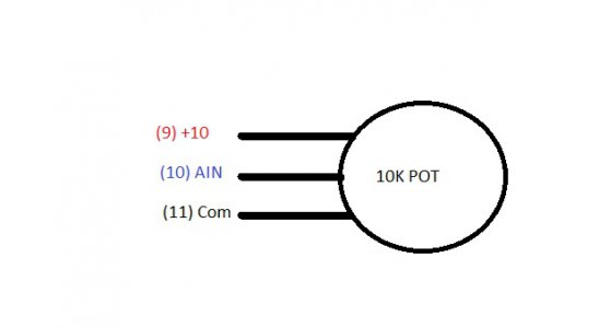
Also check you connections. All 3 wires of the pot need good connections. If one of the end wires is not connected you will get odd results. Below are two pictures. The first is cut from the actual JNEV manual, the second (my drawing) are the pot connections without the extra junk. If the control works backwards swap 9 and 11.

JNEV_AIN.jpg JNEV_POT.jpg
 
Last edited:
Well, I switched 9 and 11 and got nothing, It stayed on 5 HZ.
Switched it back, and only worked to the left.
Then I only hooked only # 9 to one of the outside wires, and it worked through the full range but still increasing HZ to the left. The
other wire, hooked to either 9 or 11 gave me nothing.
I think I am going to try another Pot tomorrow.
Could I have messed up the Pot using too much heal when I soldered it to my wires?
 
Another lost post?

As I posted earlier I think you have a bad pot. It might have been caused by soldering or it may have been DOA. Your wires for the pot do not need to be very large, #18 or #20 would be fine, actually smaller is ok also but my old fingers hate those tiny wires. You should not need much heat to solder little wires. Use 63/37 solder and flux! Check to make sure that the actual conductor part of the wire is under the screw of the VFD terminal strip and not the insulation. (Been there done that! I had that happen to me on a non-VFD project and it was a pain to find.)
 
OK, I'll check it out, and report back.
Yeah, I think my SPDT hook up must have had one wire with the insulation under the screw, only had reverse at first. Then
I switched them, and it worked.
Well that should not have mattered, just reversed what direction the switch drove the spindle.
I switched them back and It was OK,must have been the connection.

Another lost post?

As I posted earlier I think you have a bad pot. It might have been caused by soldering or it may have been DOA. Your wires for the pot do not need to be very large, #18 or #20 would be fine, actually smaller is ok also but my old fingers hate those tiny wires. You should not need much heat to solder little wires. Use 63/37 solder and flux! Check to make sure that the actual conductor part of the wire is under the screw of the VFD terminal strip and not the insulation. (Been there done that! I had that happen to me on a non-VFD project and it was a pain to find.)
 
Back
Top