Hi Michael,
Thank you for the info.
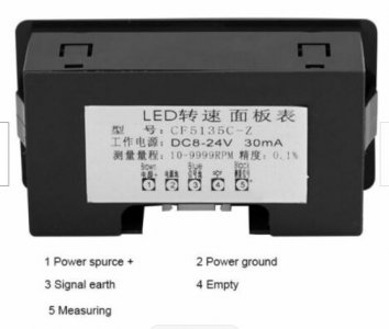
However, the display image you just sent is different from the one you sent earlier. The models numbers are slightly different by the "C" vs "D" at the end. Also the current required went up from 30mA to 40mA. I don't think it makes any difference, but just in case I mentioned it.
I understand it is difficult to get the things you need when in a more remote location. I grew up in a small town in Southwest Missouri. My town only had 749 people! Next nearest town had 11,000 people and was 11 miles away. Next nearest town had about 40,000 people and was 35 miles away. By comparison, you seem to be in a big city area. Now, I live in a big city, but the stores do not have special electronics and we all have to order them. I use Amazon or Aliexpress, China, most of the time. I too purchase components from China and commonly wait for 30-60 days. It is painful, but cheap and only very rarely do I find the part to be bad. To the US the shipping is commonly free. For fast shipping it gets expensive. AliExpress has lots of these Tachometers like you purchased and I purchased a similar one, but then later purchased one with more digit positions. When I order inexpensive items from Aliexpress, because the delivery time is so long, I sometimes order two of everything.
I initially used a "DIGITEN 4 Digital Green LED Tachometer RPM Speed Meter+Hall Proximity Switch Sensor NPN" which appears to be similar to yours and it worked. However, it will not work with a 24V supply. The maximum voltage is 15V.
https://www.digiten.shop/products/d...-speed-meter-hall-proximity-switch-sensor-npn But I purchased it at the Digiten shop on AliExpress. I have purchased several items from Digiten and they all seem to work and the last items I purchased arrived in about 20 days.
There must be a computer shop, hardware store, farm store etc near by you. They will/may have a multi-meter and various other parts, but selling them may not be their business. If you have access to a 12V automobile battery this maybe your best temporary power supply (some older cars and motorcycles use 6 volt batteries. These will not work for you.) You also remodeling the bath room. If you have a power drill with interchangeable battery you may want to check the voltage on these. Mine has 18V, but some are 12 volt. Also, a discarded tower PC will have a 12 volt power supply, but this maybe difficult for you to figure out the connections. Meanwhile you may want to order the "MEAN WELL MDR-20-12 AC to DC DIN-Rail Power Supply 12V 1.67 Amp 20W". I am not for sure where you will get yours, but I got mine from Amazon for about $21.00.
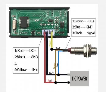
I found your sensor package on ebay, but for more money than you paid.
https://www.ebay.com/itm/384212485874?hash=item5974d946f2:g:83MAAOSw0cBgwFMV On one of the pictures it lists the connection. I will attach that image for you.
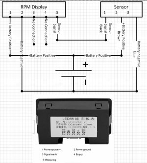
I am going to attach a the connection picture for the Hall sensor and display I purchased. It seems to have wiring connections that are similar to yours, except for the pin number. Please note that it uses only one supply and this is the best way to test things.. I suggest you also only use one. The supply can be a battery for now. 12Volts is preferred. I found that several of these sorts of electronics only really want to work on a 12 Volt supply. This is because they are intended to be installed in automobiles that have 12volt batteries. They can usually tolerate 15-16 volts because the car battery alternator puts out a higher voltage like this to charge the battery. I find drawings are much easier to communicate about rather than words, so look at the pictures I am attaching. I suggest you only use one power supply, 12 volts is preferred, but a new good 9V should work for a while.
From your last post, it seems that the sensor works at low hand turned speeds. But when you say "...reading shows quickly...." what you mean is that it shows numbers while the spindle is turning by hand, but goes back to all 0's when the turning stops or slows down? If this is correct then we know that the sensor and the display both work!!!! They are not the problem. If on the other hand if you mean that the reading shows up but if you keep turning by hand that they go away, then there is some other problem and the sensor or display may have a problem. The sensor simply puts out a pulse like signal every time it passes over the magnet. That is it. The Tach/display counts the pulses for a little while then computes the number of pulses per 60 seconds and displays this as RPM. It refreshes its counting every so often and starts over. So, if you mean "...reading shows quickly...." that the display quits working (goes back to zero and will not change, or goes to dashes) even though you continue to turn the spindle and the sensor LED continues to blink, then the display probably has a problem. Maybe you can run the spindle at slow speed (just a little faster than hand turning) first to see if speed is a problem.
But you say that when the motor is turned on the display just shows dashes. This tells me that either the sensor or display cannot work at higher speeds or that the power to the display or sensor fails when the motor is on. (The sensor power is on still the 9v battery?). If the sensor is connected to the 9V and the VFD 24v then the 24 v is probably failing or the connection to the display is poorly connected. (A poor or resistive connection will sometimes work and then stop being a good connection.) In which case we need to do check the connections. Better still is to have the display and the sensor on the same power line.
Also the ground line for the sensor and the display must be connected together.
So I have attached a sketch which I think is correct. Please look at the drawing and compare the wiring to the Digiten wiring drawing. Your display has an extra terminal and is the writing is in Chinese so I can not read it.