Tube Polisher....

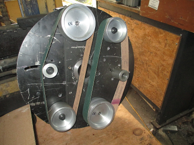
Well it's getting closer, did a test fit on the belts today. These are the wrong belts, too short, these are 40'', and it was designed for 42''. I have the 42's around here somewhere. The 40 inch would work in a pinch I think.
1663117889472.png

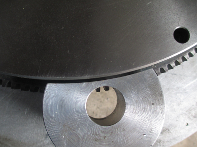
I made a measuring error on the flywheel and of course transferred that measurement to the drawing without double checking. No real problem, but I need another 1/8'' clearance in the pinion gear housings.

I need about 1/8 more clearance here.
1663027366920.png


The left side is what I have now, the right side is what I need
1663027887467.png


Change out the vice soft jaws for another set, I already had a set with a 3'' dia pocket.
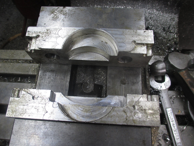
1663118295014.png

Indicate the face square to the x travel
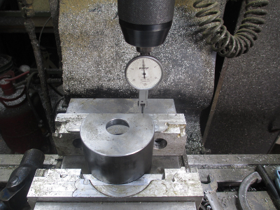
1663118348552.png

Then locate the center with the coaxial indicator.
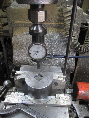
1663118432495.png

Then make chips. Not a very efficient tool path, a lot of air cutting but I'm not in a hurry and it would have required thought to fix it. If I needed more than two parts, then I might have done it differently. Took longer to set up than it did to do the work.
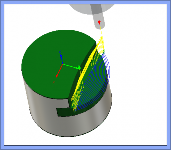
1663118591615.png

And the result.
1663118863325.png

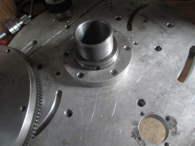
The center bearings and axle installed.
1663119184267.png

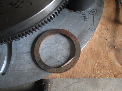
That spacer on top of the bearing nut is an interesting story. I needed a 0.245 thick spacer with a 75mm bore between the nut and the flywheel. I was looking around the shop to find a piece of stock to make it from. I found this rusty thing laying on the floor behind the drill press.
It cleaned up at 0.243 thick, and I only had to take about 0.030 out of the bore. I have no idea where it came from, but it has a new home now.
1663119611137.png

And the back side
1663119923517.png

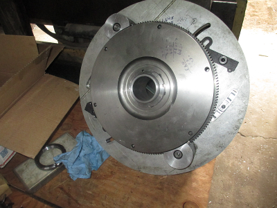
But.... I have a little problem. Nothing turns, jammed pretty tight. I think the pinion gears are bottomed out in the ring gear. That's really the only thing it can be, it turned fine until I tightened the pinion bearing retainer mounting screws. I really had no idea what the proper pitch diameters were so had to make a guess at the spacing. Too tight is better than too loose. I can just grind a bit off of the OD of the pinion gears. I also may have another problem, the main axle ball bearings are a bit loose and the disk flops around a bit. I may have to get some tapered roller bearings.

I still need to do a bit more shimming and precision fitting of some of the parts to get everything to play nice together. This was planned.

Next is the frame build. I have the pieces cut and drilled. They just need to be welded together, but I wanted this part done first so I can fit the motor and align everything.

That's all for today.
 
I still need to do a bit more shimming and precision fitting of some of the parts to get everything to play nice together. This was planned.
Jim
I'd be interested in that process as that is a part of the design - build - make it work evolution that I often struggle with. What to do when it doesn't all fit right, and how to design for that. I appreciate what you do post, and if you don't have time to put those steps online I certainly understand. Thanks!
 
I love your work Jim!

Thanks for bringing us all along with the great pictures and write-ups.

I always look forward to your posts, and you never disappoint.

Brian
 
Jim
I'd be interested in that process as that is a part of the design - build - make it work evolution that I often struggle with. What to do when it doesn't all fit right, and how to design for that. I appreciate what you do post, and if you don't have time to put those steps online I certainly understand. Thanks!
This is a placeholder to answer the above. Stay tuned. I need to go set up the lathe for the next run right now.

OK, got the lathe set up.... On with the show

In a perfect world everything would just fit as planned. But anytime you are building a machine with standard off-the-shelf parts and with your own machined parts there are always tolerances from nominal dimensions, and this needs to be accounted for.

Most of the actual design is just based on experience, I have been building machines for over 50 years so have a pretty good feel for how things are going to fit together. While I am designing the parts, I am also ''machining'' and ''assembling'' them in my head to figure out where I need to add or subtract material to allow for the tolerance stackup.

Unless you are very careful with your own machining, at best your machine tolerance is going to be +/- 0.001'' or so, and in most cases it is not necessary to try to hold tighter tolerance than this. Bearing bore fits are generally bored to the actual bearing fit measurements +/- 0.0002 or so and this is where extra care is taken to get it right. This is done by actually measuring the bearing and boring or turning accordingly to get a reasonable light press fit. Plan on reaming any holes required for shoulder screws which are generally made -.002'' diameter.

Other parts are not going to be as precision unless you want to spend a lot of setup time and very careful machining, just not worth the extra time to ''chase zeros'' IMHO. So while you are in the design process you need to think about what kind of fit you need on the final part. So many times, other than bearing fits, I will make parts slightly undersize or oversize on the critical dimensions and plan on adjusting the size on assembly to fit. Final fitting can be done with shims or machining as needed after actually measuring how the mating part tolerance stackup comes out. Most of the time I draw the parts with nominal fits, then adjust the tool offsets in CAM with the ''Stock to Leave'' function, this can be a positive or negative offset to add or subtract material as needed. Of course you can do this while manual machining also.

I have a shim kit from McMaster just for this purpose https://www.mcmaster.com/shim-kits/ring-shim-assortments-6/
and just ordered a set of these https://www.mcmaster.com/91140A800/
Both are handy to have around the shop.

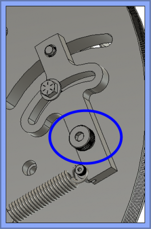
A good illustration of this is the belt tensioners. The pivot is a 5/8x1 shoulder screw. I had these laser cut from 1/2'' A36 plate. This needs to pivot and needs to float about 0.005'' above the mating part for running clearance, which means a 0.005'' shim between the mating parts at the pivot. Since I didn't have the the tension arms when I bored the holes in the mating part I had no idea how thick the A36 would actually be, it can be +/- 0.01 or so. I bored the 5/8'' holes for the shoulder screws assuming a nominal 1.000'' stackup. Knowing that on assembly I would need to put a shim between the mating parts for running clearance and would most likely need to add a shim to lengthen the shoulder screw, or would need to take a facing cut on the tension arm to adjust the thickness.

1663181400302.png

It is much easier to make these adjustments on assembly than it is to try to machine everything perfect. This of course only applies to one-off or very low volume production. If you are making hundreds or thousands of units, then you build the tolerance controls into the process. It is a lot easier to hold precision tolerances on hundreds of parts than it is on one or two. Once you have the machines set up and the part dialed in, they are generally very repeatable. It's common for our equipment to hold +/- 0.0002'' and maintain that repeatability over hundreds of parts, but we may scrap a half dozen parts in the setup process on a new part.

I hope this answers some of your questions. Please feel free to ask anything.
 
Last edited:
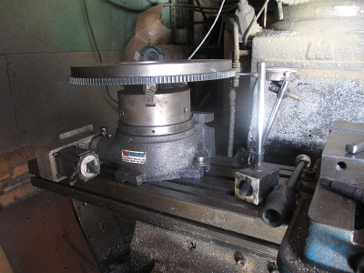
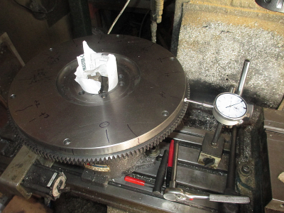
An update on the jammed up problem mentioned above. I located the problem. Turns out the pinion gears are not bottoming out in the ring gear. The ring gear is bottoming in the pinion gears. That means I need to take about 0.040 off of the 14 1/4'' diameter ring gear, and of course my lathe is a 13'' swing. So over to the mill, of course the maximum Y travel is about 13'' also, so mount up the rotary table. Then try to dial it in. Well my old cheap worn out indicator is not cooperating, so time for a new one. :rolleyes: I think I'm done for the day :faint:
 
It is much easier to make these adjustments on assembly than it is to try to machine everything perfect. This of course only applies to one-off or very low volume production.
Jim,
Thanks! My interest n machining is as a hobby, building things of my own design. Your discussion is quite helpful, in that especially for the one-off designs, it makes sense to be pragmatic about tolerances. Sometimes I guess we just need someone else to say it’s Ok to not case zeros.
 
This of course only applies to one-off or very low volume production. If you are making hundreds or thousands of units, then you build the tolerance controls into the process.

I’ll relay an interesting counterexample I remember learning about. It was an automotive rear-seat assembly, which had to fit the car’s attachment points. Rather than build in the precision, they simply completed the last weld with the assembly in place, fitting it to the car. A good way to avoid accuracy in each part of the assembly, even if, as you say, many mass-produced parts have built-in precision.
 
Always fun trying to get parts not designed to be together to play nice. I have been working the manufacturing field in one capacity or another. Many times having parts manufactured by several different companies to be assembled with parts by our own shop. The tighter the tolerances the more interesting it can get. All those allowables add up and at some point the finished or semi finished part just doesn't fit. Glad that it is a simple fix.
I was concerned about the straight bearings on the main shaft, I am pretty sure that taper will correct it, if there is sufficient spacing between the two opposing bearings.
Thanks for sharing the adventure. Love watching, brings back great memories.
 
I was concerned about the straight bearings on the main shaft, I am pretty sure that taper will correct it, if there is sufficient spacing between the two opposing bearings.
Thanks for sharing the adventure. Love watching, brings back great memories.

I also had concerns about using ball bearings for the main shaft. I spent a lot of time thinking about the problems, but what made the final decision is that I can get sealed ball bearings and can not get sealed tapered roller bearings. The other consideration is cost, these bearings are running in a horrible environment, and I expect them to be a high mortality item. Nothing like aluminum powder and fine abrasive to screw up the works. At about $9 each we can afford to replace a lot of them.

I thought about how I might seal the roller bearings, but nothing really worked due to space constraints. If the ball bearings prove to be a real problem I'll have to revisit the taper roller bearings. The other problem is the the bearing thickness, the ball bearings are 20mm thick, and the available taper roller bearings are 25mm thick so that adds 10mm to the overall thickness. Without some redesign, that will be a problem. Not insurmountable, but will require some thought.

My pleasure to share. Hopefully someone can take away something useful from these discussions.
 
I got the ring gear reduced in size.

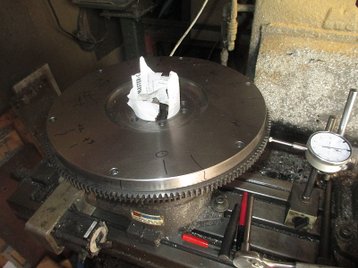
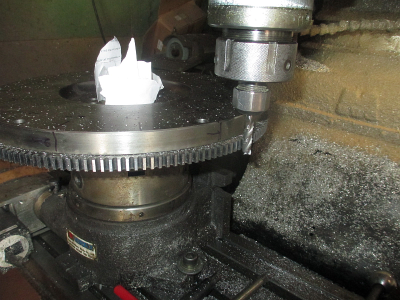
Here is the setup, only sticking up in the air a little bit. :eek: I couldn't fit it onto my plate, so I had to mount the chuck and grab the flywheel from the center.
1663286731579.png

I bought this indicator set from Amazon, cheap but it works.


I bought this indicator set because I wanted a wide stylus and this set came with 24 various styli (yeah, styli is the plural of stylus, Google said so :) ), most of them useless but it had one 1/4'' dome faced one which I needed to indicate the gear teeth. The screw adjustment rod is useless IMHO, but it came with it anyway. I'll give the set an OK for utility shop work. I should buy a Noga indicator base, got a new project next week or so, and every new project requires a new tool or two, just because...... So.... :grin:

Still using my old Harbor Freight base here, just set the new one on the shelf.

The paper in the chuck jaws are shims to adjust the chuck to dial in the OD of the flywheel. With no shims it was about 0.007'' TIR out. Got it dialed to <0.001 TIR. You find the low point, put paper in that jaw, rinse/repeat until it comes in. I think I had 5, 3, and 1 pieces of paper in the various jaws to get it to run true.
1663288026060.png

Then I checked the ring gear for TIR, well, it was not round either. But not too bad, what do you expect from a non-precision gear. ;)

1663288767381.png

Anyway, the OD is round now and concentric to the center hole. I found the low spot, and used that as my 0 point, then stepped over 0.005'' and jogged the table to make the pass, did that 4 times to take 0.020'' off of the radius or 0.040'' off the diameter. About 10 IPM, 1000 RPM, solid carbide 3/8'' roughing cutter.

1663290356249.png

It no longer binds up, but I could have taken another 0.010 off of the diameter. It works now, only a little noisey. It will wear in over time when all that grit hits it.

.
.
 
Back
Top