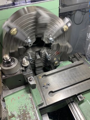
[How do I?] Turn accurate parallel faces on a disk

I emailed my friend about my being afraid of putting a 10" round in my 10" three jaw. He didn't laugh out loud but suggested that it won't take a lot of clamping force with a positive back stop. He cautioned me and stressed the importance of keeping the rotation speeds down. I think the implications are of me being a scaredy-cat time waster which would be accurate. Man, if I could only retain one tenth of the things he has taught me over the 50 years of friendship, if be a genius!
92F70E6D-BD73-4BC9-AA7A-CBA396A0535D.jpeg
 
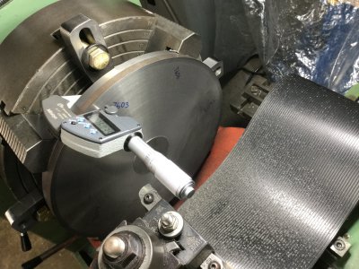
On those SHCSs are you sure you are hitting the high spot on each with the indicator? I'm not sure that each head is truly round or that there isn't lettering or such on them that would affect the high point. Cup wheel on your tool post grinder??
 
On those SHCSs are you sure you are hitting the high spot on each with the indicator? I'm not sure that each head is truly round or that there isn't lettering or such on them that would affect the high point. Cup wheel on your tool post grinder??
I turned one side of the cast iron disk. It came out good. I'm going to bore a reference hole in the middle for a dowel pin as another measuring option. I think I'm going to skim the SHCS with a sharp carbide tool after indicating them and re-indicating the heads before placing the reversed disk. The tool post grinding thing is outside of my scope of capabilities at the moment Although that's a great idea.
 
Skimming those cap screws is going to be a touchy thing. I think I'd be inclined to use a just sharpened brazed carbide tool rather than an insert. Inserts always have a bit of rounding on the cutting edge to prevent getting chips easily, takes more force to start them cutting. They also don't take well to interrupted cuts. Brazed carbide is a different mixture to stand the heat of brazing, tolerates interrupted cuts a bit better.
 
My business partner owned a automotive wheel rebuilding shop. While we were building our shop, different business, I helped him rebuild on of his tracer lathes that turned the face of the wheels after straigtening or welding. Those wheels were turning very fast and didn't have a really good grip on the back bead. I have seen two of them come flying out of the lathe when someone got too impatient with the cutting time. They flew completely across the shop before they hit the wall and started their bouncing around.

Chances are you will have absolutely no issues. I have turned large pieces at the max capacity many times and never one. Best thing is to remember, if it did let go, it will fly out in a predetermined path. Make sure you are no where near the piece, always keep the carriage between you and the piece. Just being smart about your safety, doesn't matter if it is an oversize part or a small part.
 
I'd turn one side like you have, then without moving anything I would take a skim cut on the OD to as close to the jaws as you can. That'll give you 2 reference surfaces 90deg to each other. Then flip it around and use either the flats on the jaws (if possible) or parallels/ HSS blanks to mount it with the back hard against the jaws or the parallels. Take the parallels/ blanks out then finish the job.

The stops that you made look nice but I know that there's enough movement in threads that I wouldn't trust them for dead nuts stuff.

For cutting out a center hole, grind your own trepanning bit (it's like a face parting tool), plunge in just shy of finish ID then finish up with a boring bar.
 
Thanks guys! I love the input. I did the "A-side" as described and it was good. The B-side is giving me fits. About a thou and a half is the best I have gotten. This has been a wonderful "learning experience " 35B051C0-D9A6-45FC-BBCC-9417616D3C24.jpeg
the heads turned well and pinched they have been stable. The big problem is the jaws lifting the part when clamping.
 
For the back side of the plate, mount the plate to the chuck.
Put your favorite chuck on the lathe and about a 3 inch dia bar that is just long enough to reach full depth in the jaws of the chuck on the lathe and also full depth in the jaws of the chuck you are working on.
Now do a cleanup pass on the end of that bar and it will be perfectly square and on center with the lathe spindle.
Now mount the new chuck with the back plate attached to the bar, center the chuck up good and now you can machine the od of the plate, and face it off perfectly to match the chuck. This will account for any inaccuracies in the new 4 jaw as long as you never remove the plate from the chuck. I you do remove it someday, it will loose the perfect alignment it now has.

Some times KISS works.
 
:) Live update... I'm within 0.0004" using the micrometer to measure the periphery and that is well inside my target. Thing is, I think it could be better. I used welding wire (aluminum) in the jaws, some hammering and maybe a little voodoo until I saw an approximate correction on the test indicator and I cut it. I am pretty much convinced that I should have made soft jaws for the 3 jaw. Next time!
24E83FAF-5513-46E3-AAAA-05EF6C0D24FC.jpeg
 
Skimming those cap screws is going to be a touchy thing. I think I'd be inclined to use a just sharpened brazed carbide tool rather than an insert. Inserts always have a bit of rounding on the cutting edge to prevent getting chips easily, takes more force to start them cutting. They also don't take well to interrupted cuts. Brazed carbide is a different mixture to stand the heat of brazing, tolerates interrupted cuts a bit better.
The low head SHCS were surprisingly accurate and I didn't take anymore than a one thou cut. I could still read the letters Yet all the black oxide was removed. As it played out the accuracy of the stops wasnt the problem. I think getting the half thou parallelism is good. there is about that much in a cone shape too.
 
Back
Top