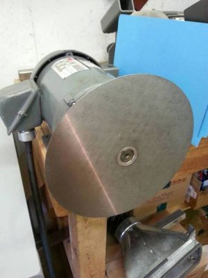
Variable speed 9" disc grinder build

melsdad

Active User
Registered
Joined
Oct 17, 2013
Messages
363
Not exactly project of the day. I have been working on this for about a month off and on. This will be a 2 h.p. 3 phase powered machine run off of a VFD.
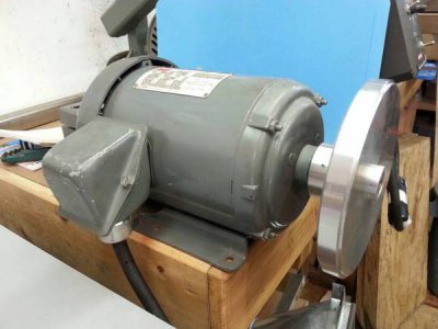
99f77c9ed92f035f3f257fcc1e88ece8.jpg
I will be using the drive that powers my 2x72" belt grinder. I will simply plug in the machine I want to run into the drive.
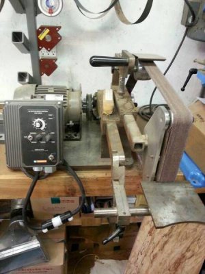
1e9dd451c1feece14b97f438730bc7e9.jpg
The hub of the machine will be aluminum with neodynium magnets pressed in to hold steel plates for quick change out of paper grits.
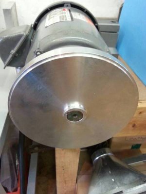
24c93fd770daedf02c5ffb5353a5d4b5.jpg
0fd0d2e9e43ffe82b89c24b8fefcdf5c.jpg

Stay tunned I will be adding pictures and get this caught up to were the project is now. This machine will also have a quick detach tilting work rest.
 
The magnets are ordered so I will get to that shortly.

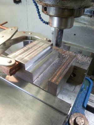
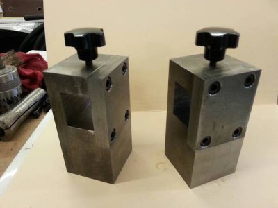
Lets start with the clamp arm posts. These Will be attached to the base plate and support the work rest. They are made of 2"x2" 1018 cold roll. I am machining them in pairs so they match each other perfectly.
0be8c448562cd55c4ae8902de809f1d8.jpg

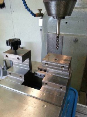
Here I am tapping the holes for the table arm clamps
ff96526aa415ae3d6a3e037ea8dac972.jpg

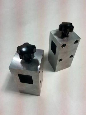
Here they are complete. I didn't get pictures of making the caps for the posts but you get the idea.
8088d5428cd42e118da053962f4aaf03.jpg
f8b99ac6ad2320afc7d2be51b11098e3.jpg
 
Last edited:
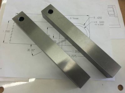
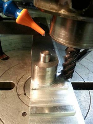
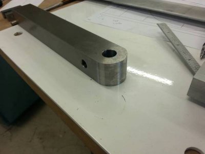
The arms for the table were also machined inpairs and surface ground so they are identical. The holes you see are reamed for a slip fit for a .500 dowel pin to locate on the rotary table.
423ab5d28ebef5f315529c3e23575002.jpg

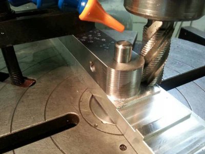
I reamed a . 500 hole in a piece of scrap aluminum to use as a fixture plate on the rotary table. There is also a hole for a s.h.c.s to hold it down to the table

f9b044b70763bf05b6a2200497676947.jpg

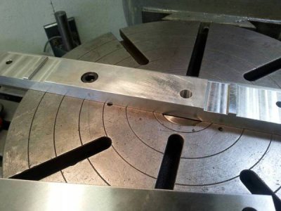
Now I can place the arms on the plate and they will repeat easily.

Roughed in.
ad5c810b9f866344777ba5845506ab3c.jpg

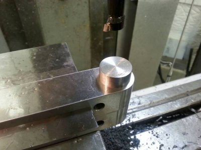
Finish pass
1e9debe70c33fc8db5ce84dd47cdc80a.jpg

Radius complete
d9620b8fc743e2536dc62b52d4820743.jpg
 
that is some beautiful machining work Brian, looking forward to the rest!
 
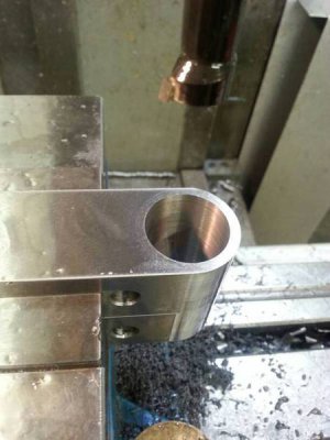
The axle on the table will be a 1" dia. Shaft. So those .500 holes need opened up to fit the axle. I removed most of the material with a 31/32 drill. Again doing these as a group so they are identical.
e72b1f8cbf6a495e9c29f7ac99963a79.jpg

Then bored the hole to size .001 oversize of the axle.
4309def7370540c67e419852f3b07d1d.jpg

Here is a cut off of the bar the axle is made of to check for fit. Just what I was shooting for...a good slip fit.
4ffe54df5626b0384841bf0d16cdee9c.jpg
 
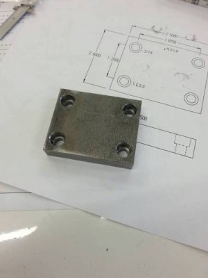
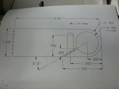
These need the slot cut in them yet so they will clamp the axle in place. Here is a picture of the print.
76837b77f97401d801835f12202c6918.jpg
 
Last edited:
Looking real good, Bryan! I like the fast grit interchangeability system.
Only have a 2hp motor? Might not be enough :rofl:
 
Looking real good, Bryan! I like the fast grit interchangeability system.
Only have a 2hp motor? Might not be enough :rofl:


Thanks Andre. Craigs list can be your friend if you keep looking for what you are after. I won't even upset anyone by telling them what I paid for the motor:whistle:

When I get her running I will try to bog her down....2 h.p. should be plenty though.

Drives start to get expensive over 2h.p. and that is the max capability of the drive I have.
 
Last edited:
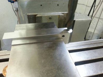
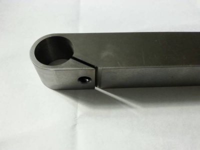
Slots are cut. I have adjustable handles that will clamp the axle in position
d504310d21d3b3a2ed26ca04b708678e.jpg
 
I decided to surface grind the table clamp arm posts. My original thoughts were to black oxide the steel parts and anodize the aluminium parts. What do you guys think?

41e26431bff10f7ba6dc776645bc5a3e.jpg
 
Last edited:
Back
Top