VFD conversion via solid state electronic components. PM1440GT, VFD, 3-phase

Hi Folks,
As I mentioned before I was adding a counter to my VFD converted PM1440GT. I finally got around to writing it up. Since I took the time to work up an Excel Workbook to generate the Gcode I posted that process at https://www.hobby-machinist.com/thr...strument-panel-gcode-in-one-quick-pass.97099/ I put some pictures there too.
Here I am sharing my efforts to automate some Gcode generation via the use of a Excel Workbook (multiple spread sheets).

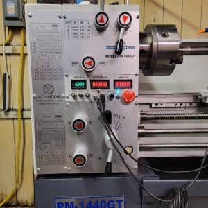
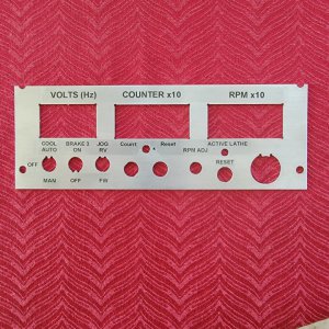
Here a couple of final pictures of the spindle turn Counter mounted in the lathe's front control panel. There is also a small three position switch located just under the counter (the center display) where one can either use it to reset the counter, to just let it run, or to have it only run after some trip event such as the Proxi. stop or Estop etc. to determine how many revolutions the spindle turns after the event. Since my Hall magnet for the RPM pick up has 10 magnets/revolution rather than just one the count is really 10x. That is the first digit on the counter display is a fraction, 1/10, of a revolution.

Also, I am attaching a circuit drawing of how the counter was attached to VFD control that I have already written up and posted. Comments are welcome. The counter has 4 leads. +power, Gnd or low, Signal in which connects to the Hall Effect sensor on the spindle (same one as used for the RPM display) and finally a reset input. If the reset input is low then the counter is set to zero. If the reset is high or disconnected then the counter starts counting. So the approach I took to using it with the proxi stop is that a signal holds the reset low until the proxi or other similar connection is interrupted. At that point the reset goes high and the counter is allowed to count. So it counts until the spindle stops. Due to my VFD Latching circuit design it works for other events such as manual breaking or Estop etc.

I will try to post some data on some data on how fast the VFD breaking works later.

Dave
 

Attachments

  • 20211222_001306.jpg
    20211222_001306.jpg
    101.2 KB · Views: 161
  • PM1440GT Instr Panel LC26.jpg
    PM1440GT Instr Panel LC26.jpg
    195.4 KB · Views: 139
  • PM1440GT VFD Counter Ckt LC25_1646.pdf
    59.6 KB · Views: 121
Hi Folks,
If anyone is interested, I improved my Panel Excel Gcode generator that I used here. It will now also do D-Sub connectors of the standard sizes. This should pretty much cover all of the D-Sub connectors.
New Template is added to the spread sheet. Are there any other connector templates that would be of value to folks?
 
Hey, this has been an interesting post. I will be doing a similar project myself for my 1440gt.
I currently have the single phase version. I honestly did not think I would need to run this off a vfd. But after running my lathe for a year. I can see the benefits.

I am not wanting anything as in depth as what I am seeing here. However, this was a well thought out project and i give kudos to the people involved. I need to get a 3 phase motor and a drive. I mainly started interest in a vfd setup because of the harsh startup on my lathe when in low to medium speed range. Also speed control would be an added benefit. Also if i decide later to add other features I can expand. I will build a separate control box to mount behind the lathe.

I will likely to do most of my controlling from a plc maybe mitsubishi, omron or similar controller, just whatever I have laying around, hopefully eliminating extra relays and or wiring. Also, most of the time changing logic or additions are quicker that having to rewire.

Can someone help me through this project.
I mainly want to be able to soft start. I do not need a break function from the drive currently so that could possibly eliminate the need for the breaking resistor and I'm fine with the motor coming to a coast.

I can perform all work needed. I have experience in all the related work that was described in the project. I pretty much do this type of stuff for a living. I have 10+ years of experience in automotive manufacturing. Which puts me around industrial robots, servo drives, electrical motor controls as well as electrical safety control systems. Most of my motion controls experience is with 480v 3 phase. I have never worked around 1 phase to 3 phase motion controls. It may not be that different, I'd just like to see what everybody thinks in a setup for this minimal design and recommended parts.
 
@ColbyB99

Thanks for the compliment. I did put a lot of thought into my design and am glad I put it all in the original enclosure so that there is no external box.

I am a pretty busy and tied up through April, but afterwards I would be happy to try to help you. Mean while you can message me with questions or post them and I will respond when I get a chance.

If you are going to purchase a new motor (3Phase) you should get one that is made to run at variable speeds. (probably set you back about $600) The stock motor that I got from PM with the PM1440GT is OK and seems to work ok at any speed for me, but not specifically designed for variable speed. Hence, while mine seems to work reasonably well, others have complained that it stutters during start up. There are several discussions on HM about which motors work well.

With the Hitachi VFD you will find that many of the functions, like brake essentially come for free. You just program them in. My circuits for the control interface to the front panel is actually very simple, but I spent quite a bit of time in my write up trying to explain the basics of the circuits for those who have less background in electronics. )I should just layout a PCB for folks and then they would not even have to worry about the circuits!) For example, when you switch Forward/Reverse/Neutral switch to Neutral the VFD can be programed to brake or to coast(free wheel) to a stop with code or via wires. I think I have mine to program to brake to a stop in less than 3 seconds. (actually 3seconds * Operating Freq/Max Freq). I really do not think you even need the braking resistor most of the time as there is some heat dissipation capability in the VFD its self. It all depends on the load and how you are operating. Anyway, you can see from my description I put in a resistor but built my own rather than getting one of those big sea slug like resistors that are really designed for use in VFDs used in control environments such as paper mills etc.

Dave L.
 
Last edited:
@ColbyB99

Thanks for the compliment. I did put a lot of thought into my design and am glad I put it all in the original enclosure so that there is no external box.

I am a pretty busy and tied up through April, but afterwards I would be happy to try to help you. Mean while you can message me with questions or post them and I will respond when I get a chance.

If you are going to purchase a new motor (3Phase) you should get one that is made to run at variable speeds. (probably set you back about $600) The stock motor that I got from PM with the PM1440GT is OK and seems to work ok at any speed for me, but not specifically designed for variable speed. Hence, while mine seems to work reasonably well, others have complained that it stutters during start up. There are several discussions on HM about which motors work well.

With the Hitachi VFD you will find that many of the functions, like brake essentially come for free. You just program them in. My circuits for the control interface to the front panel is actually very simple, but I spent quite a bit of time in my write up trying to explain the basics of the circuits for those who have less background in electronics. )I should just layout a PCB for folks and then they would not even have to worry about the circuits!) For example, when you switch Forward/Reverse/Neutral switch to Neutral the VFD can be programed to brake or to coast(free wheel) to a stop with code or via wires. I think I have mine to program to brake to a stop in less than 3 seconds. (actually 3seconds * Operating Freq/Max Freq). I really do not think you even need the braking resistor most of the time as there is some heat dissipation capability in the VFD its self. It all depends on the load and how you are operating. Anyway, you can see from my description I put in a resistor but built my own rather than getting one of those big sea slug like resistors that are really designed for use in VFDs used in control environments such as paper mills etc.

Dave L.
Hey Dave, thanks for the reply, I guess I just mainly need help finding a motor that will work with little no mods to my lathe to make it fit.

I have to say, I'm an electronics engineer by trade, your setup looks similar to what I would probably do. Its impressive. Your write up on your project was equally impressive. You spent way more time than I probably would have.

I will likely not go in depth with the controls, being I will do it all mainly in the PLC. However the safety side of the lathe cannot go through a PLC. It can, but it must be a safety PLC and they are not cheap. One safety relay for the estop and side gear cover safety switch will be enough. I'm not even sure if this lathe came with a safety relay. I dont remember when I hooked up power seeing one inside.

I will try to keep everything basic and use everything I can that is in the lathe. We have some vendors at work that we get a lot of our stuff from to do projects and repairs. Hopefully they can help to track one down and give me a good price.
 
One safety relay for the estop and side gear cover safety switch will be enough. I'm not even sure if this lathe came with a safety relay. I dont remember when I hooked up power seeing one inside.
I found a quite moment to respond.

You do not need a relay to get the safety features if you follow my electronics design. I built them in. In the original factory design this was done by a latching relay. Hence, I did the same but with transistors. See my electronic control circuit drawing and see how the e-stop, gear cover interlock etc are all in series with my latch. When current is broken the VFD is turned off and will not start again until put in to neutral, which resets the protection latch. Leaving out the VFD, the entire total cost of my system is far less than the cost of the factory design.

WRT to your motor issue, I do not have a solution for you as I simply have not researched it. I think it is a long shot to use the factory 3PH motor but maybe Matt could help you out. A single phase motor costs more than an equivalent 3 phase. Maybe you can trade/sell it off to someone. Mine works reasonably well, but other folks complain. Maybe I just got lucky. As far as a slow start up is concerned you can set the ramp up time in the VFD programing just as you can the braking time. If the motor will handle it you can also change the ramp up profile (plot of rpm vs time). Or you can just set the speed via the speed pot to a low value and then turn it up after it starts. You might want to download the Hitachi VFD manual in pdf format and search on these items. I mention the best version of the manual in my write up. But it is very long.

Dave L.
 
@ColbyB99

Thanks for the compliment. I did put a lot of thought into my design and am glad I put it all in the original enclosure so that there is no external box.

I am a pretty busy and tied up through April, but afterwards I would be happy to try to help you. Mean while you can message me with questions or post them and I will respond when I get a chance.

If you are going to purchase a new motor (3Phase) you should get one that is made to run at variable speeds. (probably set you back about $600) The stock motor that I got from PM with the PM1440GT is OK and seems to work ok at any speed for me, but not specifically designed for variable speed. Hence, while mine seems to work reasonably well, others have complained that it stutters during start up. There are several discussions on HM about which motors work well.

With the Hitachi VFD you will find that many of the functions, like brake essentially come for free. You just program them in. My circuits for the control interface to the front panel is actually very simple, but I spent quite a bit of time in my write up trying to explain the basics of the circuits for those who have less background in electronics. )I should just layout a PCB for folks and then they would not even have to worry about the circuits!) For example, when you switch Forward/Reverse/Neutral switch to Neutral the VFD can be programed to brake or to coast(free wheel) to a stop with code or via wires. I think I have mine to program to brake to a stop in less than 3 seconds. (actually 3seconds * Operating Freq/Max Freq). I really do not think you even need the braking resistor most of the time as there is some heat dissipation capability in the VFD its self. It all depends on the load and how you are operating. Anyway, you can see from my description I put in a resistor but built my own rather than getting one of those big sea slug like resistors that are really designed for use in VFDs used in control environments such as

I found a quite moment to respond.

You do not need a relay to get the safety features if you follow my electronics design. I built them in. In the original factory design this was done by a latching relay. Hence, I did the same but with transistors. See my electronic control circuit drawing and see how the e-stop, gear cover interlock etc are all in series with my latch. When current is broken the VFD is turned off and will not start again until put in to neutral, which resets the protection latch. Leaving out the VFD, the entire total cost of my system is far less than the cost of the factory design.

WRT to your motor issue, I do not have a solution for you as I simply have not researched it. I think it is a long shot to use the factory 3PH motor but maybe Matt could help you out. A single phase motor costs more than an equivalent 3 phase. Maybe you can trade/sell it off to someone. Mine works reasonably well, but other folks complain. Maybe I just got lucky. As far as a slow start up is concerned you can set the ramp up time in the VFD programing just as you can the braking time. If the motor will handle it you can also change the ramp up profile (plot of rpm vs time). Or you can just set the speed via the speed pot to a low value and then turn it up after it starts. You might want to download the Hitachi VFD manual in pdf format and search on these items. I mention the best version of the manual in my write up. But it is very long.

Dave L.
I'll have to look over your controls a little better as I just glimpsed through to see what all you incorporated. If it were me and seeing some of the things I have seen in the automated industry, I would not put anything less than a category 3 dual channel circuit with monitoring on my lathe If I was going through it and changing the basic controls. A cat2 with monitoring would probably suffice but upgrading to cat3 would not require that much more. It's probably overkill but a possible entanglement is severe enough that it justifies to me. The main reason for this upgraded safety circuit is if a component or safety feature fails then how does your machine/ controls identify it and react. All components react differently during a failure. Most will fail safe and dangerously. This is what's known as the B10 or B10d value for a component and it should be listed in the components spec sheet online if someone were to be looking for it. B10 will represent how many times the component will switch/actuate etc... before failing and B10d will represent half that value as a dangerous failure. So with each device you add, that B10 value gets cut in half. Ex. Like a similar contactor that is in my lathe. The contacts can weld which would likely cause a dangerous failure and that same contactor can have its energizing coil to go bad causing an open circuit condition on its auxiliary contacts not allowing the voltage/current to flow through and out to a motor/device which would then likely result in a safe failure. I want get into it and quote a bunch of functional safety ISO standards. Unless anybody would like to learn more, I can direct them to the proper standards for their reading and guidance. Being that I am around this stuff everyday and i see components fail all the time, it's nice knowing the safety control system saw the fault and reacted accordingly. Again, it's probably overkill for a hobby lathe at home and almost everytime I work on it, I kill power whenever I can but it will definitely make me feel and sleep better knowing when I hit that estop etc... it shuts it down without a doubt.

Anyways Dave, I appreciate you helping out and your work and write up is the stuff that really helps out people and makes a difference. Hopefully I can find a motor soon and get my project finished. When I finish my project I will likely post the upgrades to the safety circuit if anybody is interested and possibly the motion controls from the PLC.
 
Hi Colby
I agree, almost every fails at some point in life! However, I am not really familiar your requirement(s):
I would not put anything less than a category 3 dual channel circuit with monitoring on my lathe
However, more importantly would be the question: What would you "monitor" and what "conditions" indicate a problem. If it is just the e-stop, I suppose you could build a big relay system to shut the power off at the wall, but that seems pretty drastic. What is the difference between a big E-stop switch between the lathe and the breaker box and just having an on-off wall switch (30 Amps/220 Volts). I have a standard box knife blade switch to enable/disable power then I have a breaker at the breaker box. The VFD is designed for this very sort of input, but if anything goes wrong with the computer in the VFD then perhaps there are no control inputs that could do anything to straighten the VFD computer out.

So hit the e-stop and if that does not work then you would just have to throw the power switch at the wall. In the factory design they simply have a latching relay, which then causes the three phase power relays to drop out. So it all hinges on the latching relay to be safe. Yes, its contacts could weld and then you are back to the wall switch. In my design have essentially replaced this relay with a two transistor latch which provides the control signal to the VFD.

If you analyze this circuit it you will see that if the e-stop is tripped or the cover interlock switch is not conducting then the VFD is turned off. They are in series with the transistor switch and if anything cuts this current the VFD Stop signal is applied. These mechanical switches do not depend upon any transistor etc. They just interrupt the signal current to the VFD. (The VFD is a current controlled devices. No current is the off signal to the run condition. I am not for sure how you would make this "a dual" safe circuit.

I did think about what the failure mechanisms might be and the only one I could come up with was that the VFD failed in some terrible way. Transistors usually fail open and so I think all of the controls to the VFD tend to shut the VFD "Run" condition off if a transistor for that control fails open. Should a transistor fail by fusing short then something might not stop when you want it to do so, but it is a soft failure as these are the controls like Forward, Reverse, Jog e-brake etc. Then you hit the e-stop and the machine stops. Even if the latch transistors were to fuse closed the e-stop etc. still works, after all it works when the latch is on so that condition is still the same logic. So if you have to protect against a VFD failure and the wall switch is not safe enough then you may just have to live without the VFD. However, you will still want a wall power switch to back up the latching relay.

PS. A real safety concern is when you get hold of a live wire and cannot shut the power off! You need someone else to shut off the main! So I wire my breaker boxes in upside down so that the main switch is at the bottom ...... so that my wife can "reach" the main switch! (-:

Dave L.
 
Hi Colby
I agree, almost every fails at some point in life! However, I am not really familiar your requirement(s):

However, more importantly would be the question: What would you "monitor" and what "conditions" indicate a problem. If it is just the e-stop, I suppose you could build a big relay system to shut the power off at the wall, but that seems pretty drastic. What is the difference between a big E-stop switch between the lathe and the breaker box and just having an on-off wall switch (30 Amps/220 Volts). I have a standard box knife blade switch to enable/disable power then I have a breaker at the breaker box. The VFD is designed for this very sort of input, but if anything goes wrong with the computer in the VFD then perhaps there are no control inputs that could do anything to straighten the VFD computer out.

So hit the e-stop and if that does not work then you would just have to throw the power switch at the wall. In the factory design they simply have a latching relay, which then causes the three phase power relays to drop out. So it all hinges on the latching relay to be safe. Yes, its contacts could weld and then you are back to the wall switch. In my design have essentially replaced this relay with a two transistor latch which provides the control signal to the VFD.

If you analyze this circuit it you will see that if the e-stop is tripped or the cover interlock switch is not conducting then the VFD is turned off. They are in series with the transistor switch and if anything cuts this current the VFD Stop signal is applied. These mechanical switches do not depend upon any transistor etc. They just interrupt the signal current to the VFD. (The VFD is a current controlled devices. No current is the off signal to the run condition. I am not for sure how you would make this "a dual" safe circuit.

I did think about what the failure mechanisms might be and the only one I could come up with was that the VFD failed in some terrible way. Transistors usually fail open and so I think all of the controls to the VFD tend to shut the VFD "Run" condition off if a transistor for that control fails open. Should a transistor fail by fusing short then something might not stop when you want it to do so, but it is a soft failure as these are the controls like Forward, Reverse, Jog e-brake etc. Then you hit the e-stop and the machine stops. Even if the latch transistors were to fuse closed the e-stop etc. still works, after all it works when the latch is on so that condition is still the same logic. So if you have to protect against a VFD failure and the wall switch is not safe enough then you may just have to live without the VFD. However, you will still want a wall power switch to back up the latching relay.

PS. A real safety concern is when you get hold of a live wire and cannot shut the power off! You need someone else to shut off the main! So I wire my breaker boxes in upside down so that the main switch is at the bottom ...... so that my wife can "reach" the main switch! (-:

Dave L.
Hey Dave, glad to hear from you again. I apologize to anyone if this is getting off topic and if so please say.

Again, I would have to really look over your schematics.
 
Hey Dave, glad to hear from you again. I apologize to anyone if this is getting off topic and if so please say.

Again, I would have to really look over your schematics.
Hi Colby
I agree, almost every fails at some point in life! However, I am not really familiar your requirement(s):

However, more importantly would be the question: What would you "monitor" and what "conditions" indicate a problem. If it is just the e-stop, I suppose you could build a big relay system to shut the power off at the wall, but that seems pretty drastic. What is the difference between a big E-stop switch between the lathe and the breaker box and just having an on-off wall switch (30 Amps/220 Volts). I have a standard box knife blade switch to enable/disable power then I have a breaker at the breaker box. The VFD is designed for this very sort of input, but if anything goes wrong with the computer in the VFD then perhaps there are no control inputs that could do anything to straighten the VFD computer out.

So hit the e-stop and if that does not work then you would just have to throw the power switch at the wall. In the factory design they simply have a latching relay, which then causes the three phase power relays to drop out. So it all hinges on the latching relay to be safe. Yes, its contacts could weld and then you are back to the wall switch. In my design have essentially replaced this relay with a two transistor latch which provides the control signal to the VFD.

If you analyze this circuit it you will see that if the e-stop is tripped or the cover interlock switch is not conducting then the VFD is turned off. They are in series with the transistor switch and if anything cuts this current the VFD Stop signal is applied. These mechanical switches do not depend upon any transistor etc. They just interrupt the signal current to the VFD. (The VFD is a current controlled devices. No current is the off signal to the run condition. I am not for sure how you would make this "a dual" safe circuit.

I did think about what the failure mechanisms might be and the only one I could come up with was that the VFD failed in some terrible way. Transistors usually fail open and so I think all of the controls to the VFD tend to shut the VFD "Run" condition off if a transistor for that control fails open. Should a transistor fail by fusing short then something might not stop when you want it to do so, but it is a soft failure as these are the controls like Forward, Reverse, Jog e-brake etc. Then you hit the e-stop and the machine stops. Even if the latch transistors were to fuse closed the e-stop etc. still works, after all it works when the latch is on so that condition is still the same logic. So if you have to protect against a VFD failure and the wall switch is not safe enough then you may just have to live without the VFD. However, you will still want a wall power switch to back up the latching relay.

PS. A real safety concern is when you get hold of a live wire and cannot shut the power off! You need someone else to shut off the main! So I wire my breaker boxes in upside down so that the main switch is at the bottom ...... so that my wife can "reach" the main switch! (-:

Dave L.
Sorry about the last response. Some reason it cut me short and posted that without me being finished. I'm still getting use to this forum.

Like I said, I really need to sit down and go over your design/ schematics to better give you a good answer and example. Just from what you have noted, it seems safe. I thought I would bring this up being that any changes made to a machine, one would need to keep in mind the safety controls and keep them intact. I noted this mainly for someone with no experience and they were doing a similar project.

I dont want to get off subject from this post and if so please say. If you would like, DM me and I can further explain what I'm talking about as to monitoring and give you a good example.
 
Back
Top