[How do I?] Wiring Craftsman lathe for forward and reverse

Hi Clueless, it looks like the switch is fairly self-evident, I see two pairs with crossover wires already installed. Those would be the reversing contacts. A couple jumpers would need to be added.
Kit: If Clueless is correct about the blue wires being the start leg, when you connect your meter (on ohms) to them you should see a resistance change from low to high. If you see this, then reverse your test leads; you should see it again (low to high). If you see a steady reading or no reading (infinity) then you will most likely need to open the motor up
M
ps disconnect the power when doing these tests- be safe
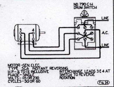
I found this image of the Cutler Hammer reversing switch on the internet. Is this helpful?

SouthBendMotorWiringDiagram1.jpg
 
First step would be to pull off the blue wire from the cap and use the meter to see if it's the same as one of the blue wires that comes out to the terminal board. Then we can go from there. What type of meter do you have? Analog type (with a needle) or digital?
M
The blue wire from the capacitor has continuity with the blue wire attached to T2. It has no continuity to the blue wire connected to T4.
The black wire on the capacitor has continuity with the T4 blue wire.
 
Last edited:
Well mostly it means that you should not need to take apart the motor to make it reverse! I believe all of the connections you need are already available. I also think it means that we have almost enough information to hook it up. What we still need is more information on the reversing switch you have.

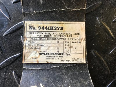
Is there a model number or even better maybe a connection diagram on the inside cover of the reversing switch your have?
Just found this!

IMG_0460.jpg
 
Last edited:
OK Kit, try swapping the two blue wires and see if the motor reverses (be sure to keep track of the changes you make)
If it does, then the battle is won; the rest is easy
mark
 
I have several of those motors that have been swapped out on my machines. Maybe not that exact model, but similar. Do watch the cap, they are often a flat pack mounted in the base of the motor. No longer available new, they can be found but usually with difficulty and usually the seller is proud of what they have. A regular cap can do the same job, just figuring out a way to mount it.

In each instance, each motor was reversible externally, without having to break things down. Make a good drawing of where each wire is terminated before disassembling anything. Then, disconnect all the loose wires, including the line cord. Unplugged, of course.

With your ohm-meter set up for RX10 or RX100, look for continuity among the several pairs. One pair will be a stable connection. The other will taper as it is read. Confirm this by reversing the OM leads. The stable one is the RUN winding. The tapering one is the START winding, which includes the centrifugal switch and the capacitor. With those four leads identified and marked, reassemble the switching network and line cord. To reverse the motor, simply exchange the two START winding leads. Confirm this a few times, whatever number you are comfortable with.

Now, to switching it. Each switch will have a nominally different contact arrangement. I received today, a switch from a Chinese source (eBay) that had an acceptable, albeit different, connection diagram. But for 10 bux??? I ordered several more, just to have on hand. (I'm a retired electrical man) Plastic, but well made, and good contacts.

In each case, there will be two contacts that reverse and a third that makes up in both directions. The connections for this are widely covered herein and there being so many different switches, I won't specifically explain each one. The end result is to switch the RUN winding and reverse the START winding. Both at the same time, of course.

Bill Hudson​
 
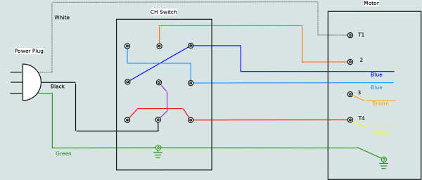
The thing that makes this slightly more complicated than typical motors is the thermal overload. To preserve that function (which I think is a good thing) the connections get a bit more confusing. Here is my best guess at the connections you need using the switch you have. Note there are 4 jumpers needed between terminals on the switch. Brown and Yellow wires must be connected at the motor end and both blue wires must be spliced and brought out to the switch.

CH_Reversing_with_Cman_motor.png
 
Nice Clueless, and in color no less
I haven't quite puzzled out how the 240 volt hookup would go however. Let's hope the two blues are in fact the start wires
 
The 240 volt conversion starts to get into the drifty area, wherein the number of connections expands considerable. There are two RUN windings. They are connected in parallel for 120 volt and in series for 240 volt. Most often, on older motors, the START winding is straight 120 volt. When connecting to 240 volt, one end of the START winding is tied to the center of the RUN winding. For 120 volt, the START winding connects in parallel, with the CENTRIFUGAL switch and capacitor as part of the series circuit, of course. It can be reversed, on 240 volts, by swapping one lead of the START winding from one line to the other. But this only works on 240.

This is getting complicated, I know. For simplicity's sake, it might be better to keep everything the same as with 120 volts. Just moving the one wire for 240 volts as you wish.

The only real concern here is to keep the polarity of the two windings correct, relative to each other. If you get them mixed up, it is fairly easy to correct. With the motor unloaded, leave one RUN winding open. Start the motor on 120 volt. Note the rotation. Swap the connections and start the motor again on the other winding, again on 120 volts and noting direction. This identifies the polarity of each winding. There is a more serious way using a lantern battery and a compass, but is not usually necessary on a single phase motor.

Now, as concerns the "overload", it connects in series with everything. Simple as that. Take the black wire in the line cord to the overload. From the overload, go to the motor. Think of it as the same as the line fuse or breaker. It is time rated so it doesn't trip immediately, like a fuse. But otherwise, the same. I often leave it disconnected when using an external overload switch. But don't have one for each machine, and most motors don't have an internal overload. In normal circumstances, it won't trip until locked rotor. Full stall. If it trips when running, you have a gross overload. Or you are starting far too often.

My lathe is a 101.27440, an earlier model than your's. I use a Baldor 1/3 HP motor. I don't do heavy cuts, but this motor is plenty sufficient for what I do, even with frequent restarts. It does not have the internal overload. I prefer the TEFC(farm duty) enclosure so as to keep chips and dust out. The Craftsman motor is similar in design, I just happen to like the "farm duty" motor Baldor produces. It is wired 120 volt on a dedicated circuit. I debate going to 240 volt, have debated for years. The biggest issue is having a work light available on the same circuit.

Bill Hudson​
 
I suspect it is not possible to wire that motor for 240V using that switch with 1) reversing, 2) keeping the thermal overload functional and 3) disconnect both hot leads when off. I believe I can do both 1 & 3 if I give up thermal overload on the start winding in one direction. I also think I can do 1 & 2 but not disconnect one of the hot leads when turned off. Anyone care to take on that challenge?
 
Back
Top