TAKE THE BELOW INFORMATION WITH A GRAIN OF SALT
i have no experience with King equipment or their electrical systems...
i looked but could not find a factory diagram or schematic for your unit
the low speed is run in the delta configuration, the high speed is run in the Wye configuration
most likely the connections will all be made at the motor and brought back to the switches for speed and directional control
that is, unless there are contactors or relays involved with the control system
here is how the control circuit works in most equipment i have encountered....
(this unit may have a less sophisticate control)
the green or green yellow striped wire is connected to ground
a transformer (may) provide control system voltage below 575v-
simply put, the upper green button on the upper left side will supply power to the control circuit indirectly through the normally closed stop switch.
the normally open momentary green power switch would pull in a contactor or relay when the switch is depressed, as well as supply power to both the directional switches
the directional switches would supply power to pull in one of a set of interlocking, reversing contactors (to ensure the motor is not reversed at high speed)
dependent on which speed is selected, the corresponding contactor will pull in
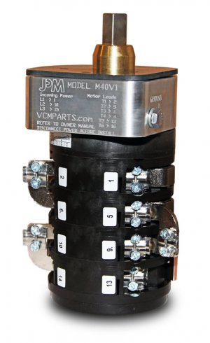
conceivably the U1, V1, W1, U2, V2, W2 connections would be made at the motor with the identified wires
3 control wires could be connected to the U1,V1, W1 motor terminals and shorted together at the directional switch for Wye operation
3 wires would connect to U2, V2, W2 motor terminals and the Delta contactor/relay
all this being said, you system may all be controlled by switches- without the use of contactor or relay
in that case, it is of great importance to prevent the motor from being reversed when in the high speed setting
(i think that's why there is an extra switch in your system that i can't seem to account for at the moment)
if you can provide pictures of the controls opened up, i may be able to guide you better-
all i can offer now is conjecture