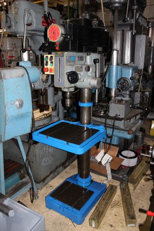
WIRING HELP!! on my newly aquired King model KC401-V2F 3 phase 575

I don't see a transformer either, if it has one you could test the whole system safely by powering just the transformer, and latching the low and then hi contactors in turn and checking continuity between the line wires and the motor wires
M
 
I don't see a transformer either, if it has one you could test the whole system safely by powering just the transformer, and latching the low and then hi contactors in turn and checking continuity between the line wires and the motor wires
M
HI

I will try and get some more pics tomorrow.

Thanks
 
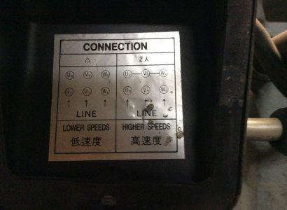
Mlalonde, I started my posts based on an assumption that the previous owner changed, or began to change the wiring only to convert the machine to 220 volt single phase. The obvious choice to do so would be to install a VFD motor speed controller, which would use the existing three phase motor with single phase input to the VFD. The cam switch was there to change the motor wiring between wye and delta configurations for a two speed setup. The cam switch should be the only existing electrical control part not used in the new wiring.

So, I guessed the six wires to the cam switch was the only puzzle you needed help with.

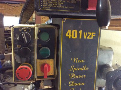
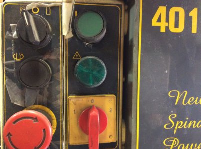
If this is correct, please get us the manufacturer name and part number off the original cam switch. I don't think it is the same as the similar JPM cam switch you showed because the JPM switch is a 0-1-2 whereas your switch (as shown in the picture of the control box front) is a 1-0-2 which must be a different mechanism. Once we have the electrical schematic of the switch the wiring terminal connections will be easy to figure out.
 
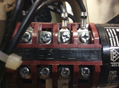
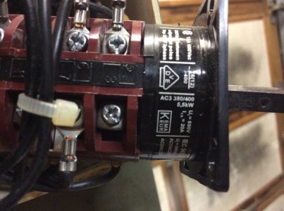
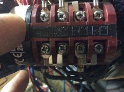
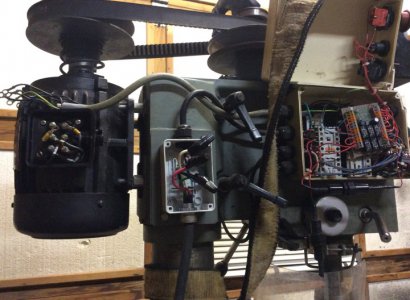
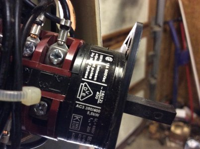
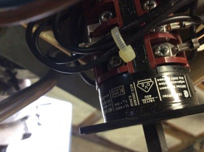
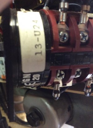
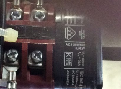
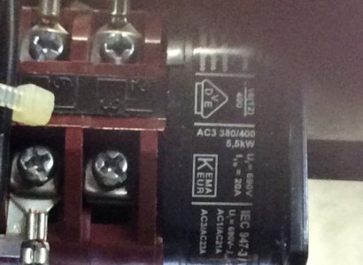
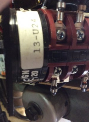
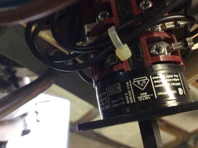
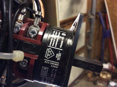
Ok so here is a couple pics of my Drum switch. I also checked every wire and number on the switch. It is as follows

The 6 black wires are numbered 1 through 6

No. 1 wire goes to terminal 4 on drum switch
No 2 wire goes to 7
No 3 Wire goes to 12
N0 4 wire goes to 1
No 5 wire goes to 6
No 6 wire goes to terminal13

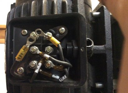
There's 3 other black wires that go to the drum switch. drum switch 1.jpgdrum switch 2.jpgdrum switch 3.jpgMotor wires.jpgmotor cover.jpgKC wire=ing route.jpgThey come from inside the control box.
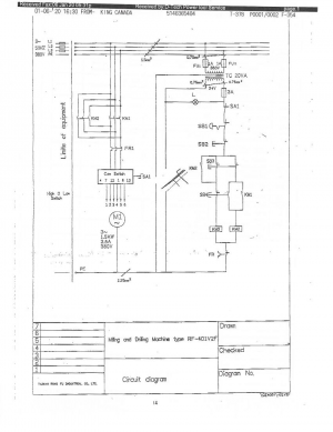
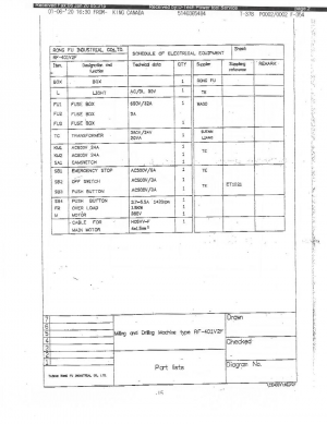
KC wiring diagram.pngKing Canada wiring diagram.pngKing_401_KC-401V2F_Mill_Drill_334075_01.jpg
T1 to terminal 14 on the drum switch
T2 to terminal 2
T3 to terminal 5
 
Thanks mlalonde, but I still need to determine the internal wiring of the switch, which can only be done with the company and model number of the switch so I can track down their technical diagram, or I need the switch in my hand so I can trace the operation with an ohm meter. If you have the JPM switch to replace the original I can tell you how to hook it up and it will work fine. The manufacturer's data sheet shows how the internal connections are routed in the different switch positions. The switch on your King is a center off, but the JPM switch is ccw off. The pictures you posted show external jumpers on the switch terminals that will not work with the JPM switch. Just take a lot of pictures of the printed information around the mounting end of the switch.
 
Thanks mlalonde, but I still need to determine the internal wiring of the switch, which can only be done with the company and model number of the switch so I can track down their technical diagram, or I need the switch in my hand so I can trace the operation with an ohm meter. If you have the JPM switch to replace the original I can tell you how to hook it up and it will work fine. The manufacturer's data sheet shows how the internal connections are routed in the different switch positions. The switch on your King is a center off, but the JPM switch is ccw off. The pictures you posted show external jumpers on the switch terminals that will not work with the JPM switch. Just take a lot of pictures of the printed information around the mounting end of the switch.

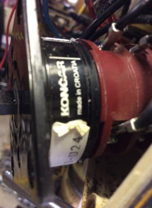
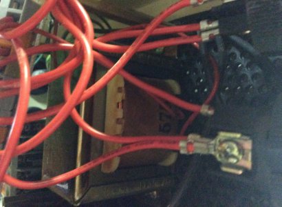
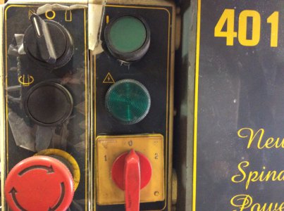
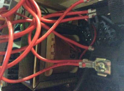
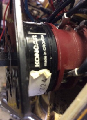
Ok Fellas here some more pictures. I took a picture of my control panel switches as I believe they may be different from the 1st pics I sent. Also on the transformer the only thing I could see was on was side it was 24 and on the other side it was 575 . The drum switch is a Koncar . Didnt see any numbers on the transformer accetpt the 24 on one side and the 575 on the other. Hope this helps! s1.jpgs2.jpgs3.jpgs3.jpgs4.jpgs5.jpgswitch3.jpgswitches.jpgswitches.jpgswitches2.jpgtransformer 24.jpg
 
Ok Fellas here some more pictures. I took a picture of my control panel switches as I believe they may be different from the 1st pics I sent. Also on the transformer the only thing I could see was on was side it was 24 and on the other side it was 575 . The drum switch is a Koncar . Didnt see any numbers on the transformer accetpt the 24 on one side and the 575 on the other. Hope this helps!


switch3.jpgtransformer 24.jpgs5.jpgs4.jpgs4.jpgs3.jpgs2.jpgs1.jpgswitches2.jpg
 
It does help! I located the Koncar factory catalog and now I 'm verifying which wiring diagram to use. I'll post the factory diagram with simple instructions for you.
 
It does help! I located the Koncar factory catalog and now I 'm verifying which wiring diagram to use. I'll post the factory diagram with simple instructions for you.
That would be awesome!!!!!! TKS
 
Switch wire Motor
Terminal number wire

4 o------------- 1 --------------o U1
7 o------------- 2 --------------o V1
12 o------------- 3 -------------o W1
1 o------------- 4 --------------o U2
6 o------------- 5 --------------o V2
13 o------------- 6 --------------o W2

3 phase Power
5 o--------------- L1 ( order not important; if motor
2 o--------------- L2 (rotation does not match indicator
14 o--------------- L3 ( switch any two leads)

Reconnect the conduit with the 7 wires to the motor wiring box. In wiring box on motor remove all 6 hex nuts from the connection studs. Pair up each motor wire with a switch wire on a stud and secure with hex nut. The studs are electrically floating so it doesen't matter what order.

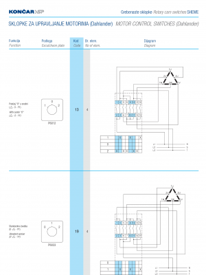
Here is the drum switch manufacturer's wiring diagram, the key to hooking it back up properly. Notice the code 13. It's from your switch picture. It's the only way to select the correct diagram from many.

Screenshot_20200119-182058.png
 
Back
Top