2014 POTD Thread Archive

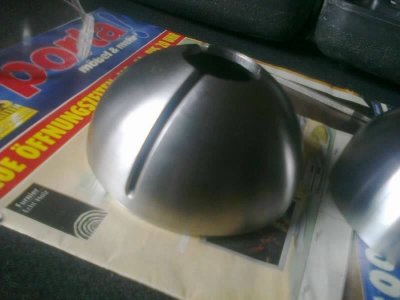
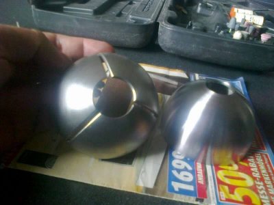
Well, I made a slotted hollow stainless steel sphere for the company sphero robot, a challenge because at certain time, there is not room for holding, also the chamfers requested on the slots needed full five axis milling. Then runout on the mating halfs needed perfection...surface finish all along the sphere surface needed an algorithm to calculate variable speed....a simple slotted sphere can get really interesting.

image.jpg image.jpg
 
Well, I made a slotted hollow stainless steel sphere for the company sphero robot, a challenge because at certain time, there is not room for holding, also the chamfers requested on the slots needed full five axis milling. Then runout on the mating halfs needed perfection...surface finish all along the sphere surface needed an algorithm to calculate variable speed....a simple slotted sphere can get really interesting.

I think that is not so simple. Great job!
 
Last edited:
A video of those spheres being machined would be quite interesting, if you get a chance next time feel free to post one.:))
 
Unless you buy some pricy blades I don't think their runout is anything to be proud of.
I usually over engineer or over spec anything I build, it serves me well in business "no comebacks" ... but it can be classified as a sort of disease too ... :lmao:
 
A video of those spheres being machined would be quite interesting, if you get a chance next time feel free to post one.:))
Dear everyone, I stopped placing videos for special customer related advice (I sometimes machine things the customer cleans the chips off the machine) but I will ask the customer. Meanwhile search for Mexcoaero or syaminab on youtube, you will enjoy what I do when Im not grounded by nat sec or the patent keymaster.
 
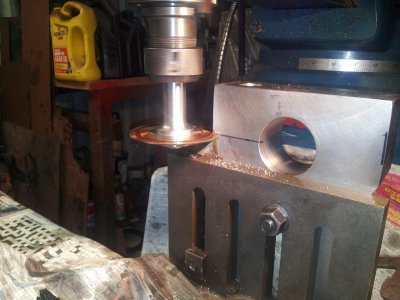
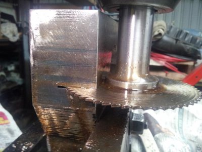
Seems to work fine no slippage of saw to arbor, blade limits me to a 27 mm cut. Mild steel 50 mm
I increased the rpm later after the video
Will get a bigger blade.
Short vid here, bit shaky but you get the idea
:)) dd
[video=youtube;96-2MS3XhnM]https://www.youtube.com/watch?v=96-2MS3XhnM[/video]

Start.jpg Cutting.jpg
 
Last edited:
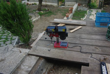
As promised in post #1602, here is a good way to void all warranties:

deck1.jpg

deck2.jpg

Try to make the same with a Bridgeport or a Cincinnati, if you can! :lmao:
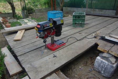
Now who is curious to know why the belt guard of my drill press has a hole in the top can see the reason.
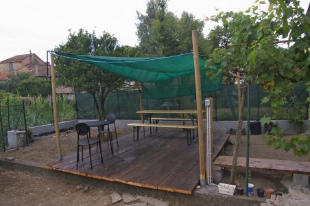
The boards are the ones we use for scaffolds in the building yards, 5×25 cm (2×10").
Here is a view of the same deck in June 2009, when I made it: the walkway still had to be done, the rosemary bush was not yet there and the boards (more than 200 euro for them!!!) were still straight…
gazebo01.jpg

Using spade bits I made 21 counterbored holes for M8 carriage bolts, head 20 mm, sink for ~ 6 mm in the wood. The stem hole is 10 mm, and below there will be a 50×5 mm iron bar to support the patch, with 12 mm holes. I left some clearance so the wood and the iron can move freely.
And I hope the insects will break their teeth trying to chomp the iron!!!

deck1.jpg deck2.jpg gazebo01.jpg
 
As promised in post #1602, here is a good way to void all warranties:

I like your drill setup, you just need a magnetic base and your all set if you ever build a steel deck, did you put some brass in front of those grub screws or are you leaving marks in your column when you move the head?
Nice work around for changing speeds..!:))
 
I like your drill setup, you just need a magnetic base and your all set if you ever build a steel deck, did you put some brass in front of those grub screws or are you leaving marks in your column when you move the head?
Nice work around for changing speeds..!:))

That was a magnetic base for wood! :rofl:
The column of these drills is just a water pipe with some chrome over it, so marks are not a problem. When/if I find a more serious column I'll think to brass on the screws.
BTW, this morning I had the funniest part of the work: spelunking under the deck to place washers and nuts on the carriage bolts.
The village undertaker helped me: he is used to see people lying face up into a hole in the floor… but generally his customers curse and swear a lot less than me!
:roflmao:
 
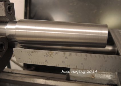
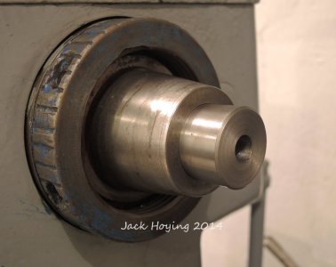
Made a real project with the new taper attachment last night. I made a Morse 4 1/2 taper plug (dead center holder) for my Clausing 5914 spindle. Eventually, I hope to buy a MT 2 reamer for the internal hole, but for now, I just bored it to 1/2" and plan to insert a hardened point that I will grind in place.

It took three tries to get the taper just right, but I'm happy with the final result.


taper07.jpg

Inserted into spindle, cut to length, faced and bored in place. (the length was chosen so the face with be nearly in line with the dog drive plate)
taper08.jpg

I finished the basic construction of a taper attachment on my Clausing 5914 lathe today. I still have some cleanup and painting to do on it, but it's mechanically finished. I used a 26" x 1" rod that I had on hand, along with some bronze bushing for the slide. The rest is pretty basic construction. I tried it out on a piece of metal that I had and the finish is very nice and smooth.
The brackets are 3/8" x 3" metal. There aren't any critical measurements here, so if you make one, just go with the materials you have on hand.
Like all taper attachments, the main work involves setting up the arm to cut an accurate taper, so that will take some experimenting with. I have to make a Morse 4 1/4 taper for my headstock, which will be my first real project on it.

View attachment 77567


View attachment 77566


Here's a short video of the test project (making wire instead of chips)
[video=youtube_share;N8JbfrUDDOY]http://youtu.be/N8JbfrUDDOY[/video]

Jack
Fort Loramie, Ohio
taper07.jpg taper08.jpg
 
Back
Top