2014 POTD Thread Archive

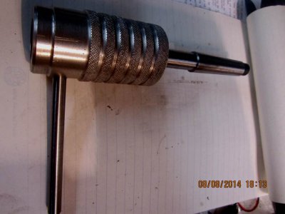
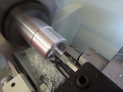
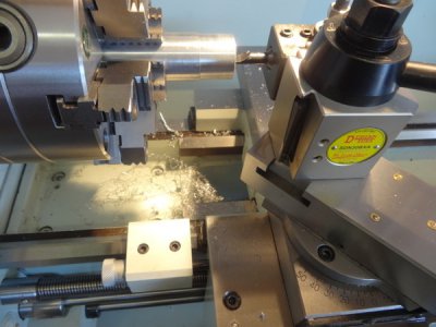
Had a good day today, made a Die holder.
I had a MT2 dead centre with a chewed up point so I cut the conical part off.
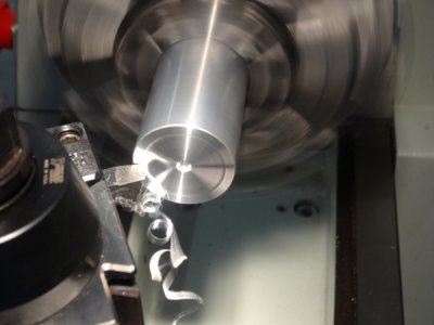
Using a MT3 to MT2 adapter in the spindle I faced the end, I thought it would have been harder than it was.
Drilled it out at 12mm by 50mm deep.
Turned down a 50mm section of 20mm bar to an interference fit and pressed it in with locktight.
Replaced the MT2 into the adapter and centre drilled the end of the bar to to turn it between centres down to 15mm using a shear bit to get a fine finish.
The die holder is a chunk of cast aluminium turned down, bored to 15mm to slide on the shaft.
I had to bore from each end as my boring tool wasnt long enough and much to my surprise the bores met if not exactly then not enough out to notice. It slides on the shaft with no play.
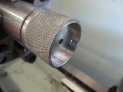
A 5mm grub screw holds the die in place to prevent it from slipping.
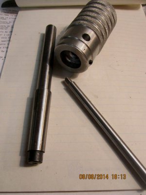
die holder 2.jpg
die holder 1.jpg
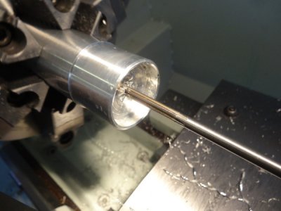
In action making the 6mm thread for the tommy bar.
You will notice that the aluminium is covered in little black dots - hydrogen porosity unfortunately.
As the casting is not the strongest of materials due to the porosity I drilled through the casting and screwed the tommy bar to the opposite side so as not to strain the thread.
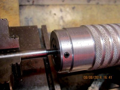
die holder 3.jpg

die holder 1.jpg die holder 2.jpg die holder 3.jpg
 
no machining, but I replaced an O2 sensor and wheel bearing on the car. I was particularly proud of using my press to get the old bearing out and the new one in, until I went for a test drive and realised that I did the wrong side :( That'll teach me to assume a problem part is the same part that's been a problem before! Nevermind, I'll put turn the radio up for the drive tonight and order another one from Rockauto ($16 with shipping!).
 
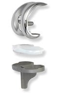
Didn't exactly do this as had it done. Saw it before it went in what a nice machining job. I offered to supply my own to save some coin but that didn't wash.
Hope to get back in the shop soon to actually make something.

John

ARTIFICIAL KNEE.jpg
 
Nice work. Looks great.

Mike.


so i was riding to work the other day, looked down, and the end part of my foot peg was gone. so, left me no choice but to build some new ones. i often find myself lacking in the artistic area, so the are kinda plain; not the hardest thing to do, but it was a fun quick project that i was able to do in an afternoon vs several days. love the sense of accomplishment upon finishing something.

here is the old peg that was left,
View attachment 81579

here is a shot of the underside, can't see it when its on the bike, but i was really just playing around.
View attachment 81580
and on the bike. still need to make the piece to match for the shifter knob.
View attachment 81581
 
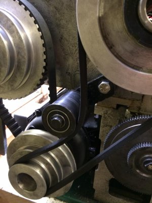
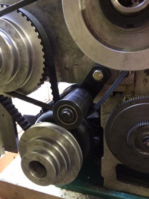
I finally got around to doing the belt-idler mod on my G0602 lathe:

377EA552-1C9D-4B33-A42F-E9AAA94FB18B_zpsytmrvy2p.jpg

21071F48-01D0-4623-BF6F-E0107DD502DE_zpseitjvhdt.jpg

I believe Fabrickator originally came up with mod, I got it from the ProjectsInMetal website.
I can not believe I waited this long to do it - changing the belt position on this lathe with the original setup is a *royal* pain. With Fabrickator's mod, it's a breeze and literally can be done in under 30 seconds with no pinched fingers. It was also so easy to do.
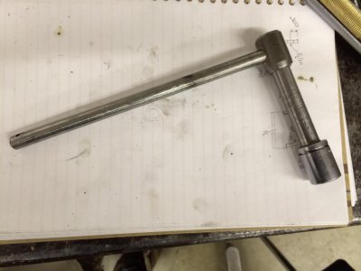
Since I used a 3/8 bolt and all the other wrenches for the lathe are metric, I also decided to slap together a special wrench for loosening and tightening the adjuster:

A933A147-9BA8-4F68-B5EE-7AE980BA655A_zps4mfzrvku.jpg

It took me longer to make that, than to do the mod...

377EA552-1C9D-4B33-A42F-E9AAA94FB18B_zpsytmrvy2p.jpg 21071F48-01D0-4623-BF6F-E0107DD502DE_zpseitjvhdt.jpg A933A147-9BA8-4F68-B5EE-7AE980BA655A_zps4mfzrvku.jpg
 
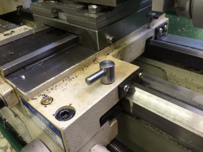
Made a quick-adjust saddle lock lever for my G0602 lathe today:

667263FC-FF92-4F66-A027-3955DDA0E5F2_zpstfszpyu3.jpg

1BC51516-F54F-488D-B0DF-14AB500D7F1D_zpsgiikgzsd.jpg

Another one of those "I can't believe I waited this long to make it" mods...

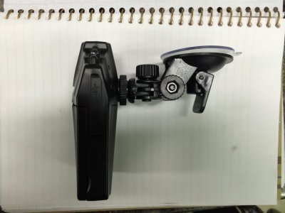
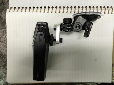
Also had to modify the bracket for a dashboard-cam dvr I picked up at a hamfest. My wife wants to use it to monitor the bird feeders and apparently the designers assumed it would only ever be used on a slanted windshield, because it can't be mounted to a normal window pane and point forward (the camera extends past the plane of the suction cup):
FF5B7805-95EB-442E-9D69-F6F1658D38E0_zpsqoocpiox.jpg

Ten minutes to make an extension bracket and I think I'm good:
95F5FD5F-A7CC-440A-8427-59DAC1E8AFD8_zpsdkh9wglt.jpg

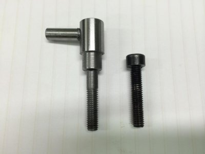
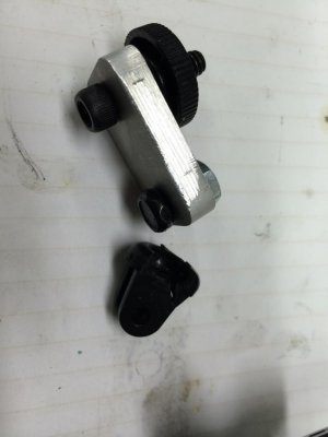
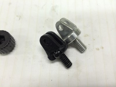
Then I realize the top bolt is apparently just molded (or press-fit) into the plastic standoff, because it snaps when I drop the assembly:
0803C255-5F1E-4E20-88A0-D6CA2BD76169_zpsrbarcpgb.jpg

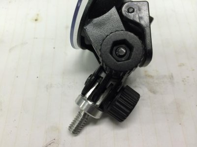
Back to the shop, and an hour later I have this:
438A3AEC-E615-4BF6-ACE8-BE9FBF234B91_zps9mtramsb.jpg

CCABA250-107D-4F82-B1D6-AE31CCEA0CA6_zpseailjuzo.jpg

Seems to work, and wife is now happy (which is the most important part)...

667263FC-FF92-4F66-A027-3955DDA0E5F2_zpstfszpyu3.jpg 1BC51516-F54F-488D-B0DF-14AB500D7F1D_zpsgiikgzsd.jpg FF5B7805-95EB-442E-9D69-F6F1658D38E0_zpsqoocpiox.jpg 95F5FD5F-A7CC-440A-8427-59DAC1E8AFD8_zpsdkh9wglt.jpg 0803C255-5F1E-4E20-88A0-D6CA2BD76169_zpsrbarcpgb.jpg 438A3AEC-E615-4BF6-ACE8-BE9FBF234B91_zps9mtramsb.jpg CCABA250-107D-4F82-B1D6-AE31CCEA0CA6_zpseailjuzo.jpg
 
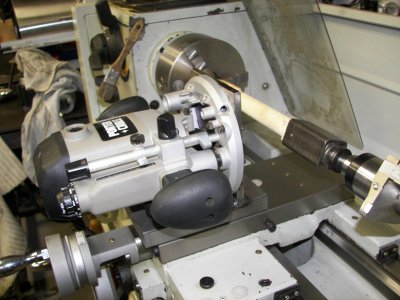
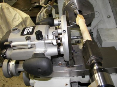
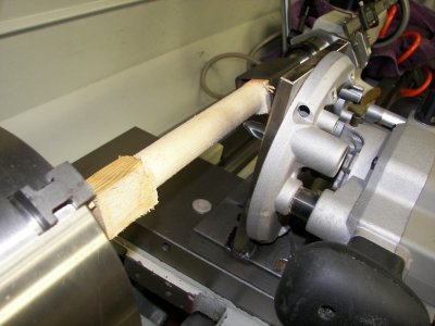
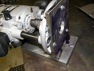
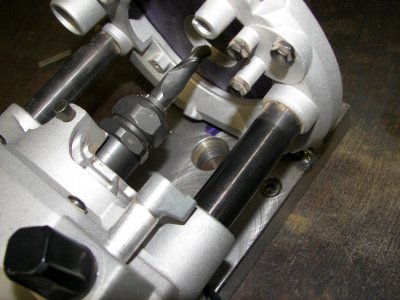
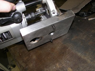
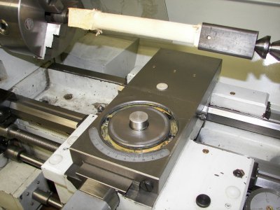
Made an attachment to hold my wood router on my lathe.
100_9493.JPG100_9494.JPG100_9495.JPG100_9496.JPG100_9497.JPG100_9498.JPG100_9499.JPG100_9500.JPG100_9501.JPG

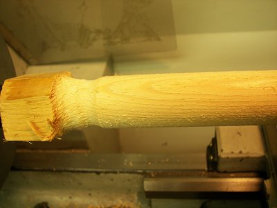
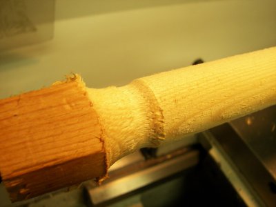
I made it to turn round wood on the lathe. I did a test piece in soft pine and it cut great. Think it will do much better in hard wood. I ran it using a .500" ball end carbide router bit and it cut smooth. I did a comparison cut on the left end with a sharp turning tool. The router cut much cleaner. Eventually I will make a tracing attachment for the lathe to use with the router. And yes it takes hours to clean the lathe after cutting wood.

Jeff

100_9493.JPG 100_9494.JPG 100_9495.JPG 100_9496.JPG 100_9497.JPG 100_9498.JPG 100_9499.JPG 100_9500.JPG 100_9501.JPG
 
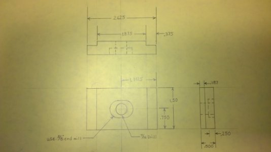
My tail stock has been driving me nuts. It is not the original clamp but is the original square headed bolt. Some one made a clamp plate from 1/4" plate. It not only bends under pressure, but the bolt head was not captured to keep from turning and it took a half dozen turns to get it to catch and tighten. this was frustrating with all the drilling on the steady rest parts. so I took a piece of 3/8" bar stock and made a new one . it is great. it now takes less than a quarter turn to tighten and slides easy when released. this is how it should work. drilling is much easier now. the print is hare in case anyone wants to do the same.


Mark

tailstock clamp.jpg


tailstock clamp.jpg
 
Glad it worked out for you. It only took me one speed change to do something about changing the way Grizzly designed it!!


QUOTE=kizmit99;220239]Made a quick-adjust saddle lock lever for my G0602 lathe today:

View attachment 81754

View attachment 81755

Another one of those "I can't believe I waited this long to make it" mods...

Also had to modify the bracket for a dashboard-cam dvr I picked up at a hamfest. My wife wants to use it to monitor the bird feeders and apparently the designers assumed it would only ever be used on a slanted windshield, because it can't be mounted to a normal window pane and point forward (the camera extends past the plane of the suction cup):
View attachment 81756

Ten minutes to make an extension bracket and I think I'm good:
View attachment 81757

Then I realize the top bolt is apparently just molded (or press-fit) into the plastic standoff, because it snaps when I drop the assembly:
View attachment 81762

Back to the shop, and an hour later I have this:
View attachment 81768

View attachment 81769

Seems to work, and wife is now happy (which is the most important part)...[/QUOTE]
 
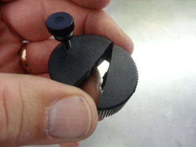
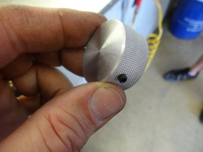
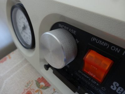
The wife came to me the other night and informed me that the plastic knob on her Lymphatic Sequential pump for her leg broke. I told her no problem, I have a $6k dollar lathe in the shop just to make a .49 cent part.:lmao:

This is what I started with.
2iv0j8g.jpg

Started with a piece of 1.5" 6061 aluminum and turned it down and faced it off.
24awzcy.jpg

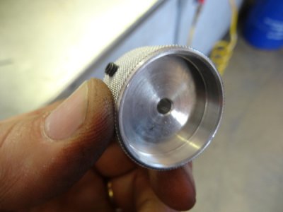
Drilled a hole and then bored the backside out .250" deep.
105749i.jpg

Tried out my carriage stop to get the depth consistent.
axzfd5.jpg

Drilled and reamed a hole .1875" for the stem.
24fmpg6.jpg

Threw some knurls on the outside.
2v8quet.jpg

Parted it off, faced it and drilled/tapped for a 8-32 set screw.
2rwayhe.jpg

Underside.
2qu7ww2.jpg

Completed and installed.
oidfmx.jpg

You know what they say, happy wife-happy life. No kidding.

Mike.
 
Back
Top