2015 POTD Thread Archive

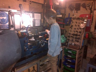
got bit of time in shop with my boy.
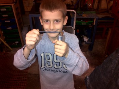
knocked up little handle to get bit more leverage on allen keys.
made to fit his hand size, one end does up to 4mm other side 5-8mm.
did it all himself with me supervising.
just used bit of scrap ali.
cut to length in vice deliberately at angle so he could have go at facing off.
think smile says it all.
tay1.jpg tay2.jpg
 
Definitely cool to get your boy making chips. Those loose sleeves are a bit scary, though.
 
first pic is set up was taken after work done.
he had his sleeves rolled up whilst using it.
he wanted it running for pic which is why his arm is straight down at his side in pic.
couldn't take pic whilst he was doing it as stood over him with hand on stop button which i do on any power tools they use.
 
Way to go Dad.
Teach him the right way first.
Then he'll be kicking you out of "His" shop later. :D
 
Hey,

Have been learning to use the mill

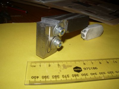
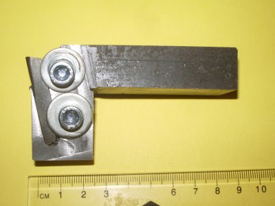
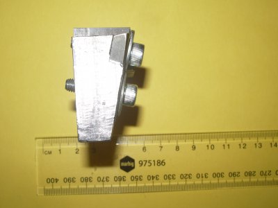
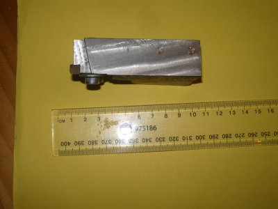
Tee nuts, hold down clamps are done, and now a tangential tool holder for the lathe is underway.

Am stunned at how useful the mill is and how much am enjoying learning how to use it.

Next is toolmakers clamps, small hammer, machinists jacks, tool height gauge for lathe, 37/47 spur gears to cut metric threads on imperial lathe, sharpening jigs and at the far end on the distant horizon there are rotary table, dividing head and other goodies.

Am reading Guy Lautard and George Thomas books and HSM and MEW and ME magazines and workshop practice series of books.

Bill
 
I needed to make some of my new tools capable of moving around for space saving so I started installing casters on the shear and finger brake. Had some 1/2" angle iron that was left over from another project so it got used for the shear. Installed some 7/8" bolts to use as stabilizers if I needed. I only raised the working height of the machine 1/2". Had to build a electrolysis unit to fit the large scale items I was working with. For the finger brake I shorted the original legs to match the height of the casters. I made new base plates that weld to the legs and bolt to the casters. Now I need to get the press on casters......

It looks to me, in the electrolysis tank photo, like your work piece is sitting on (in direct contact with) the rebar. Do I understand that correctly? I thought that the two had to be physically separated and immersed in electrolyte for good results. Please elucidate.
 
Hey,
Have been learning to use the mill
Tee nuts, hold down clamps are done, and now a tangential tool holder for the lathe is underway.
Am stunned at how useful the mill is and how much am enjoying learning how to use it.

Next is toolmakers clamps, small hammer, machinists jacks, tool height gauge for lathe, 37/47 spur gears to cut metric threads on imperial lathe, sharpening jigs and at the far end on the distant horizon there are rotary table, dividing head and other goodies.
Am reading Guy Lautard and George Thomas books and HSM and MEW and ME magazines and workshop practice series of books.
Bill

Sounds like you're well and truly hooked!

Ain't it great!?!?!?!?!
 
It looks to me, in the electrolysis tank photo, like your work piece is sitting on (in direct contact with) the rebar. Do I understand that correctly? I thought that the two had to be physically separated and immersed in electrolyte for good results. Please elucidate.

I have them setting approx 1/4" above the rebar. I use small pieces of wood between them and the floor of the container to keep the distance.
 
Yep hman you are right its great having a mill.

The tangential holder is finished - fairly ugly but it works. Next one will be much prettier and take 1/3 of the time.

Some nice lateral thinking in this thread

http://www.modelenginemaker.com/inde...ic,712.45.html

Had to actually have a go before I could properly understand what I'd been reading on the net.

..... and did I mention that it works - am quite happy.

Bill

1 Isometric.JPG 2 Front Viiew.JPG 3 End View.JPG 4 Plan View.JPG
 
Can you post more on how you made this? It is on my project list.

Jeff
Basically I just started with a piece of round off the shelf 2in od, then turned down a boss that would later go into the square piece. I used my mitutoyo pro 3600 digital protractor and set zero on the vise jaw and tilted the round stock at a 7deg angle using a v block in the mill vise, cut a 3/8 wide slot deep enough so the bit would be in it all the way across the 2in diameter. Drilled and tapped 2 holes for the clamp, I removed the angle so the face was parallel with the spindle. I did the clamp in the same fashion, tilting it at 7deg to mill the slot. Then removed the set angle and drilled the clearance holes. The 45deg angles on the outside of the clamp were done with my mitsubishi face mill just because I could. The square piece is surface ground flat and parallel, cause I could lol, it also has 45s cut on all corners again using the mitsubishi, I drilled the hole up to 1inch then bored it out the rest of the way. Drilled and tapped for a set screw in the side to hold the bit holder in place. Also milled a small flat for a reference mark on the top. On the round bit holder I used a technique turning the part and making a pass, turning and making a pass to get that cool almost prism look, done on the surface grinder, taking only a couple tenths off. I will probably redo that part to make finer lines. I just looked at someone else's design and made my own, pretty much winged it, the square was also something that was already on the shelf I was just making a little block that was flat and parallel, it ended up being flat enough that my gauge blocks will wring to it on all faces. If you want to know more ask, I'm happy to explain what I can. Like I said earlier you have to add relief to the base square so the tool will have side clearance, you could do this in the bit holder itself but would just make things more difficult with the compound angle that you would need to set up twice.
 
Back
Top