2016 POTD Thread Archive

That's a slick backstop, Franko! How well does it stop the arrows (that miss)?

It works pretty well, Jon. Using bullet field points, my light (30 lb) re-curve bow will will stick them about 2 layers deep up high and some bounce back about a foot or two when I miss low.

My compound bow (set for about 60 pounds) will stick them all the way through the 4 layers, protruding a couple inches out the back.

This backstop replaced a slightly smaller one that had 3-layers of carpet. Three layers is enough. I just used four because that's what the pieces I had cut to. It works well to catch the misses so they don't stick in the fence or bounce all over the yard – and it doesn't damage the arrows.

I don't shoot broad heads at my targets. My back yard is in a neighborhood and besides tearing up the targets, they are very dangerous. When I first got the compound bow, I was using a hand-held release. As I was aiming, I let off the pull just enough that it jerked the release out my hand and fired an arrow over the fence. I got a wrist strap release and have taken measures so that will never happen again. The target is in front of a higher section of my fence and I don't shoot if anyone is in the yard next door.

I don't really hunt, I just like target shooting. The target shown in the picture is for my re-curve bow. It is big, and needs to be, as I'm still learning how to shoot a re-curve bow. I have a couple cube-type targets for the compound bow. I'm a much better shot with it.
 
Finally completed the lawn mower blade grinder [finished up making a guard for it and mounted the on/off switch so it's not just hanging off the motor], continued from http://www.hobby-machinist.com/thre...in-your-shop-today.14637/page-229#post-387478

Some people asked how it works, I've annotated some pictures on what the various parts are and how it gets adjusted. The annotations are either red lines or circles with a letter next to them

First, an overall shot with the guard. That triangular thing hanging off to the right side of the picture catches the ground off material, as the grinder spins in reverse from most common grinders.
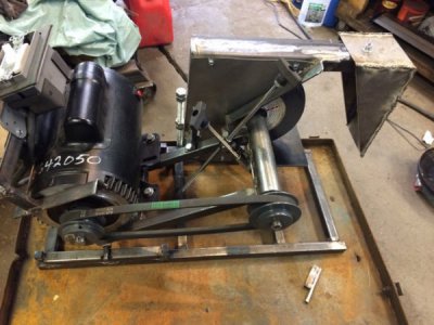
IMG_0543.jpg


This shows the platform where the blade would slide back and forth to be sharpened (just above "A"). the platform can be adjusted left and right and is held in place with two bolts and fender washers. The platform can be adjusted up and down via the screw "B". These shouldn't need to be adjusted much anymore, as the idea is to get the right end of the grinding platform to be on the centerline of the grinding wheel in the plane that it moves along when adjusting for the wheel being worn down.
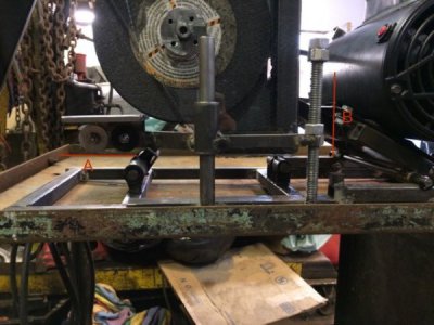
IMG_0546.2.jpg

This shot, the "front" of the machine, shows the front support "C" for the grinding wheel axle. It consists of a shaft and next to it (just to the left) is a threaded rod which is used to adjust the height of the grinding wheel from the platform as the grinding wheel wears down. "H" is a pivot point so the platform the grinding axle is part of can rotate a bit as the machine is adjusted for grinding angle and wear on the grinding wheel.
IMG_0545.2.jpg


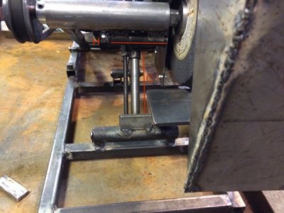
This is the other side of the machine from the first one. The circle labeled "H" is the end of the pivot point from the previous picture, and "C" is the side view of the front support. If you follow the line, you can see the knob used to adjust the wear height of the grinding wheel.

"F" is a threaded rod, used to adjust the grinding angle. "G" is a pivot point which connects "F" to "C", and together with the base, form a triangle so the grinding axle is firmly supported and can't move while the machine is in operation.

"E" is the frame holding the motor and grinding axle together, and it slides along "D" as the grinding axle is adjusting for wear height and grinding angle.
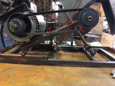
IMG_0544.2.jpg

The grinding angle isn't perfectly maintained as you adjust the wear height, because "G" and "H" aren't in the same spot and the other end of "E" doesn't move in the same way as "G" or "H", so the angle will change just a bit as you adjust the machine for the grinding wheel wearing down. Initially I had come up with a more complicated and very top-heavy arrangement that would maintain the grinding angle exactly as it is adjusted for wear, but I decided that it was just to much for what the purpose and precision of the job required.

So far, it's done a good job on the couple of test blades I've used it on, but I'll probably have to work on how the grinding platform "A" connects to it's support, as it will vibrate up a little and then get into the grinding wheel...maybe instead of fender washers, maybe something "C" shaped so the platform is more securely gripped (poorly described, but I think it should work better).
 
A celebration is in order. I just finished my very first machining project and did it on my restored Sheldon lathe. I had a piece of ??? Shaft 2" in diameter about a foot long. I found center on both ends and drilled a center on both ends. I then chucked it in the lathe and used a dead center on my tail stock and turned it to 1 3/8" for 5 inches. I then set up my steady rest and bored the 4" turned part to 5/8". I then parted it off in 3/8" thick pieces making some wheel washers for an old WC Allis Chalmers Tractor. I have looked all over trying to find originals with no luck. The parting process worked much better than I thought it would. I used a 1/2" Hss bit that I ground to a parting tool. I ground the narrow parting tip just long enough to get through the material left on the shaft. It took much longer than it should have but I'm so excited that it all went off without a hitch.
 
Good job AR. It feels great being able to make stuff out of blobs of metal. I just started a couple months ago and also like to take my time to make things. Just today, I went a little too fast bending some sheet metal making a shield and wound up bending facing parts the same way instead of one part one way and the facing part the opposite way.
 
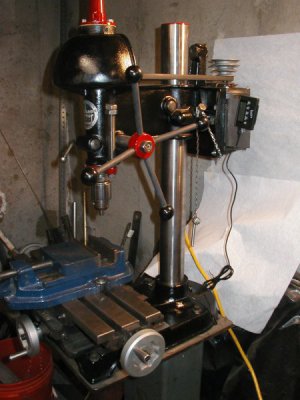
Today I finshed getting the Walker Turner drill press back together and added a DRO. I did a quick milling of a slot I needed on a bracket. It worked great. All noises are gone and finish is improved. Amazing what difference a missing collar and a couple shims can do. But then I also painted it to look a bit better too.

P1010015.JPG
 
Before, I would just eyeball it on a bench grinder like this:
View attachment 126458

It got them sharp, but not at a consistent angle, didn't do it evenly over the whole blade and wore some excellent grooves into the aluminum support on the bench grinder. Doing it with an angle grinder probably would do a better job than this.
When I saw this image and your explanation I thought, "Gee, I've always had better luck with an angle grinder and a file than a bench grinder." :)
...

I have a landscaping company and I sharpen a bunch of blades every week, this will make sharpening blades easier and more consistent then the old method I was using.
That makes more sense now. Sharpening the blade makes mowing much easier and produces a better result. Making this will both improve your sharpening and your process efficiency, making it more reasonable to sharpen blades more often. Time well spent. :)
 
When I saw this image and your explanation I thought, "Gee, I've always had better luck with an angle grinder and a file than a bench grinder." :)
...


That makes more sense now. Sharpening the blade makes mowing much easier and produces a better result. Making this will both improve your sharpening and your process efficiency, making it more reasonable to sharpen blades more often. Time well spent. :)

Yeah, it's totally overkill if it was just for sharpening the blade on a mower used only once every week or two. If I had a good angle grinder before I started making it (and thought of using it), I might have stayed with just using it...
 
Back
Top