2016 POTD Thread Archive

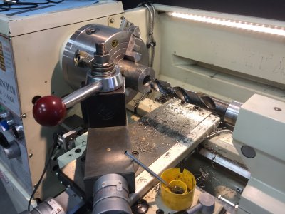
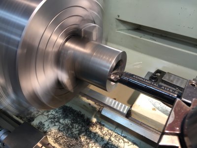
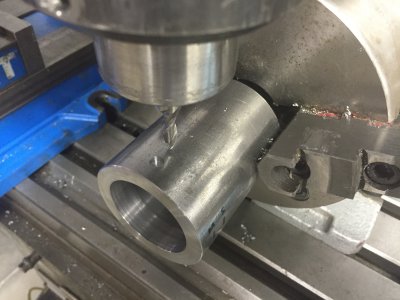
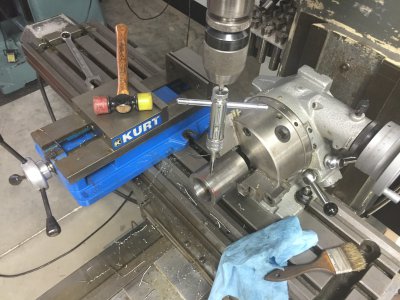
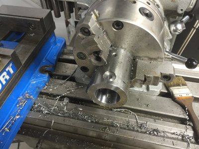
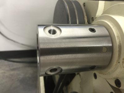
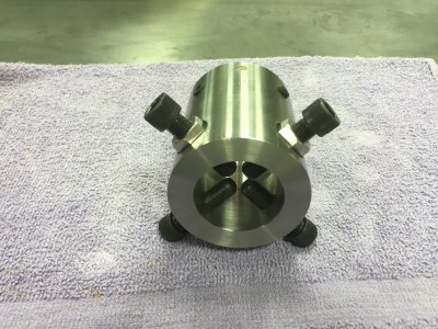
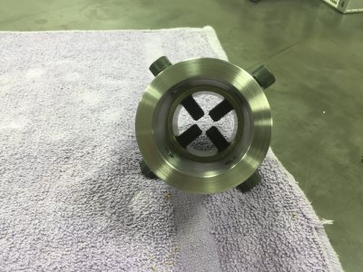
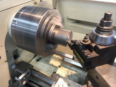
Built the Sider body after shift. The P sensor was awesome to work with during the boring operations. The lathe's new control system worked very well and speed adjustment a breeze. The stock used was 2.5" CR. Cut to 3.250" and faced both ends for a overall length of 3.200". Stepped drilled to 1.125" and bored to ID of spindle. Secondary bore to OD of spindle X 1.875". A rotary was used to drill/tap and counter bore the spider. A small 1/4" re-ground end mill was used to set the depth of two stacked earth magnets for the Tachometer pick up. This measurement was 0.375 from the headstock end of spider. The four 5/16-24 set screws where at 90* increments (45* to magnet) and 0.750 from headstock end of spider. The other four 3/8-24 spider bolts are 0.5625 from end of spider to afford clearance once the cover is on.
IMG_1393.JPG IMG_1395.JPG IMG_1437.JPG
IMG_1438.JPG IMG_1440.JPG IMG_1441.JPG IMG_1444.JPG IMG_1447.JPG IMG_1451.JPG
Still need to modify the 3/8-24 cap screws with brass or bronze tips, but really needed to get the spider body mounted to have a working tachometer.
A long day after shift but had a blast with the new control system on the lathe.

And YES for those of you wondering, I cleaned up the mess, like it never happened. Haha!
 
Nice job on the spider Paco. Are the two magnets 180* apart? I have one of those tach's on the way so I need to get going on the spider for my lathe.
 
Nice job on the spider Paco. Are the two magnets 180* apart? I have one of those tach's on the way so I need to get going on the spider for my lathe.
Hi Dan,
Thanks, no not in two locations but stacked and secured with green loc-tite in one location. You will need to place them with the correct pole facing out. If your pick-up has a little indicator light on the end where the wire goes into the pick-up, you can figure out which direction to embed the magnets. I could be wrong, but more than one location of magnets would give a false RPM (the more magnet locations the faster RPM readout) with this style of Tach. Once I have the pick up mounted, I plan on verifying the RPM using a laser reflective type tach for comparison.
 
hey paco, why haven't you cut the top threads of your tool post nut off yet? also looks like you have quite the washer stack under it too. nice job on everything as usual
 
Yea, I do need to do that, Jury is still out on keeping the CXA. I like the rigidness but a little oversized for a 14". I need to extend the threads to eliminate the washers for this one to work.
 
I have a bxa on a 12inch, my tool holders sit at about the same position as yours do, near the bottom, I say keep it. its in the same saying as "theres no replacement for displacement" there is no replacement for the rigidity that it provides. a smaller less rigid tool post means you may loose a little hogging ability, adding time to some jobs....
is there anything you have found that that tool post keeps you from doing or a tool you cant use?
ive even hung a tool holder below the compound top to get the tool on center....
 
No real limitations, other than larger size. I have two of them, the one shown is Armstrong, the other is Aloris, but needs some TLC. I did have to cut a new base to make it work in the compound. I have cut my inner wrist a time or two on the exposed threads,so when you mentioned it I kind of chuckled. I will address the extra length when I get some time.
I purchased these back in early 2000 when you could still find plenty of good deals on eBay.
BTW, your scraping skills are awesome.
 
Last edited by a moderator:
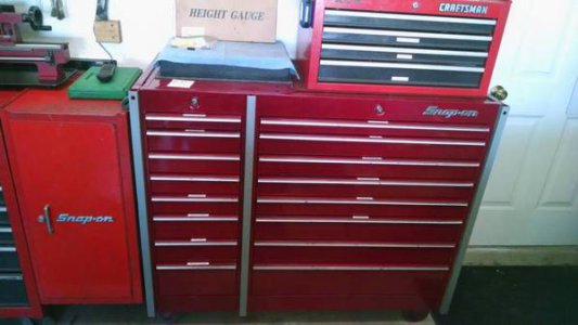
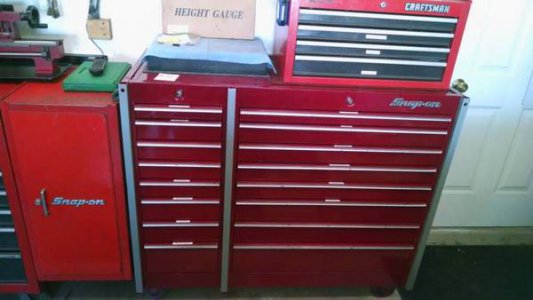
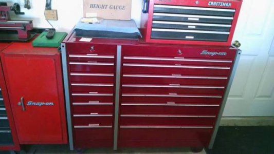
Wrapped up the tool box refurb:

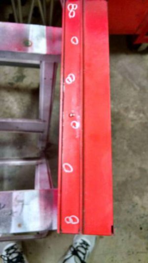
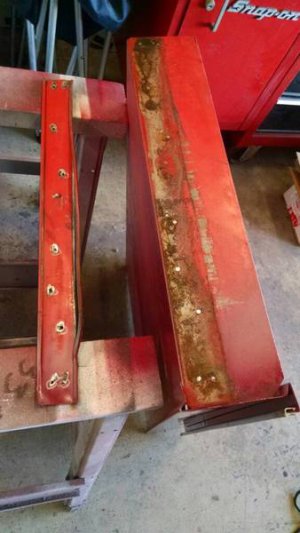
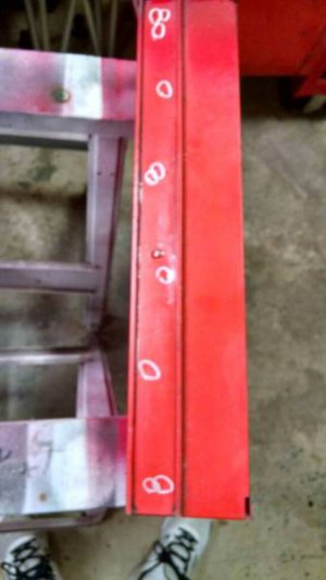
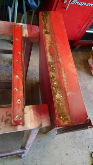
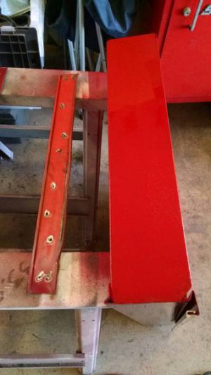
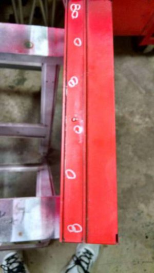
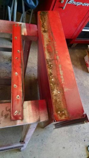
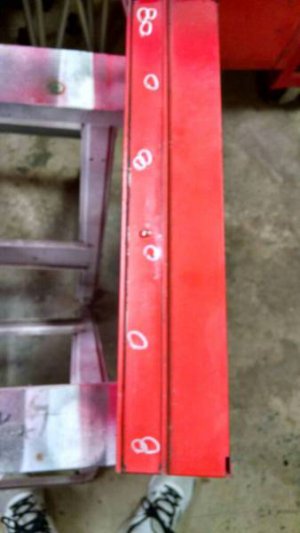
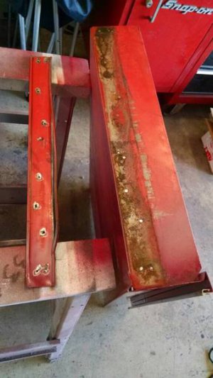
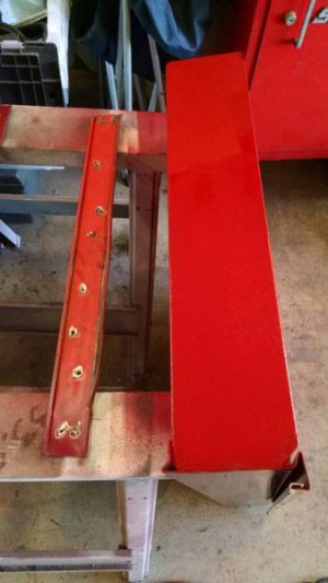
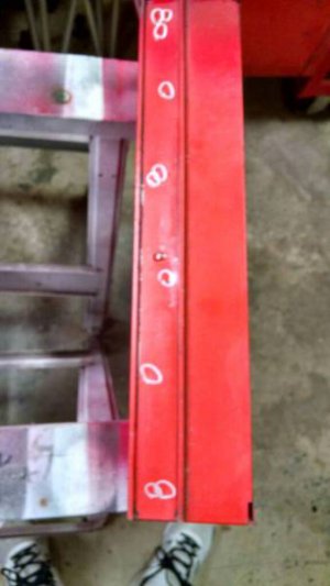
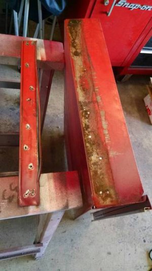
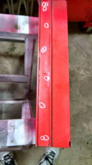
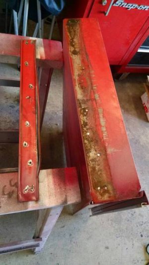
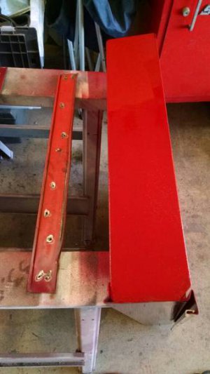
Marked the spotwelds and ground them down to remove the friction slides:
a400ee794b20c08c131f2dd5458c51ac.jpg

a5290810b356a1f2b6d5045fbb418fc1.jpg

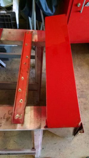
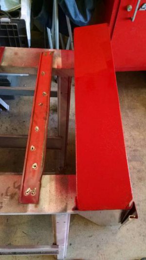
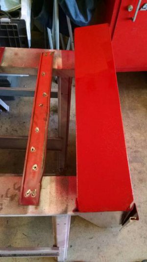
A little touch up paint, not the right color, but will keep the rust at bay:
398910b9128de721138102cc0a7952c4.jpg

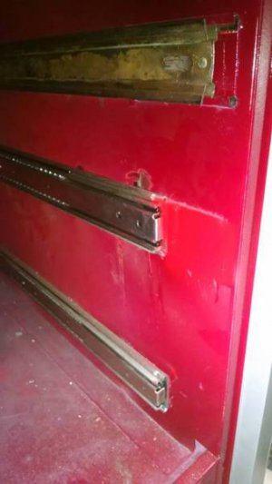
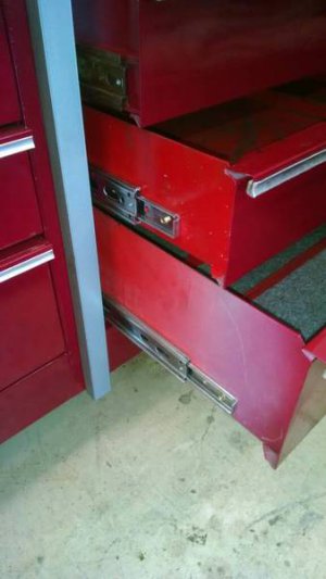
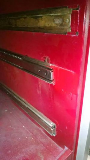
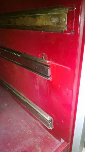
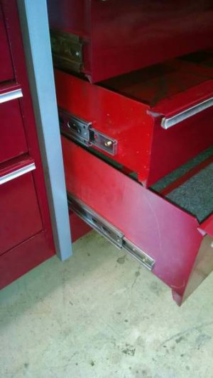
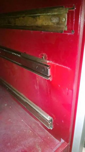
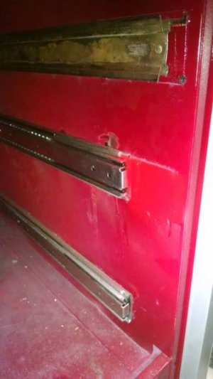
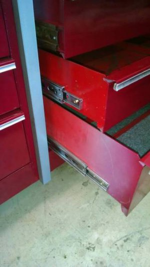
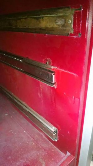
Mounted the ball bearing slides with stainless pop rivets to che cabinet:
a0de717f378040c32912e2dbd76e0bae.jpg

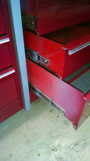
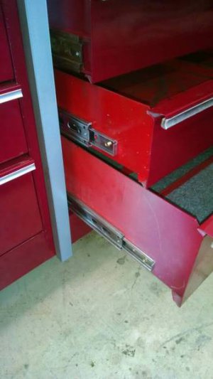
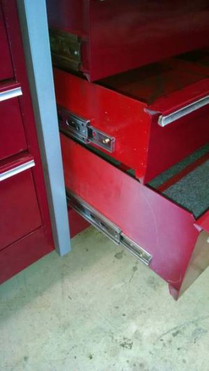
Replaced the drawers.... now the bottom 2 are ball bearing:
468dc152590a0a127ede8841e50e1e0e.jpg

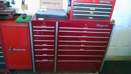
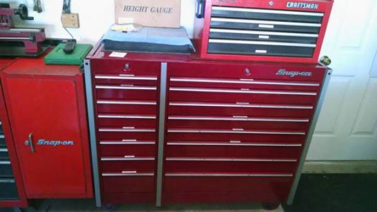
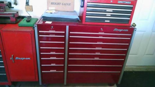
Finally completed:
da84d8b63c60f07afa5bf82eff3f0bdb.jpg

Sent from my SM-T217S using Tapatalk

a400ee794b20c08c131f2dd5458c51ac.jpg

a5290810b356a1f2b6d5045fbb418fc1.jpg

398910b9128de721138102cc0a7952c4.jpg

a0de717f378040c32912e2dbd76e0bae.jpg

468dc152590a0a127ede8841e50e1e0e.jpg

da84d8b63c60f07afa5bf82eff3f0bdb.jpg

a400ee794b20c08c131f2dd5458c51ac.jpg

a5290810b356a1f2b6d5045fbb418fc1.jpg

398910b9128de721138102cc0a7952c4.jpg

a0de717f378040c32912e2dbd76e0bae.jpg

468dc152590a0a127ede8841e50e1e0e.jpg

da84d8b63c60f07afa5bf82eff3f0bdb.jpg

a400ee794b20c08c131f2dd5458c51ac.jpg

a5290810b356a1f2b6d5045fbb418fc1.jpg

398910b9128de721138102cc0a7952c4.jpg

a0de717f378040c32912e2dbd76e0bae.jpg

468dc152590a0a127ede8841e50e1e0e.jpg

da84d8b63c60f07afa5bf82eff3f0bdb.jpg

a400ee794b20c08c131f2dd5458c51ac.jpg

a5290810b356a1f2b6d5045fbb418fc1.jpg

398910b9128de721138102cc0a7952c4.jpg

a0de717f378040c32912e2dbd76e0bae.jpg

468dc152590a0a127ede8841e50e1e0e.jpg

da84d8b63c60f07afa5bf82eff3f0bdb.jpg

a400ee794b20c08c131f2dd5458c51ac.jpg

a5290810b356a1f2b6d5045fbb418fc1.jpg

398910b9128de721138102cc0a7952c4.jpg

a0de717f378040c32912e2dbd76e0bae.jpg

468dc152590a0a127ede8841e50e1e0e.jpg

da84d8b63c60f07afa5bf82eff3f0bdb.jpg
 
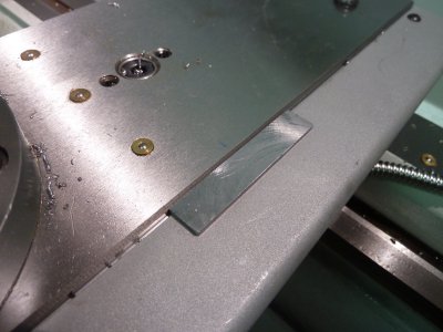
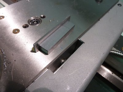
When I was doing the DRO install on my lathe I added an access slot to the x axis scale mount so I could still use the lock feature. The first time I used the lathe I realized that the slot was going to collect a bunch of swarf so I made a cover. I used steel in the hopes the weight would keep in place. It works and it still easy to grab the edge for removal.

carrage lock cover1.JPG

carrage lock cover2.JPG
 
thanks for the complement paco, lol I thought you may have been sliced once or twice, I USED to have my vice studs sticking up like that, I use 5/8 instead of the 1/2 inch bolts most use, and I cut myself once on them, super sharp, I bled pretty good, I ended that right away by milling them flush to the nut.
 
Back
Top