New PM-25MV Mill

How much for one of your enclosures
I am afraid it would be prohibitively expensive for me to make one where I wanted to make a half decent hourly wage for the time I spent on it.

Though materials were probably around $500 or so and the extra tools were in the $300 range.
 
I am afraid it would be prohibitively expensive for me to make one where I wanted to make a half decent hourly wage for the time I spent on it.

Though materials were probably around $500 or so and the extra tools were in the $300 range.
It looks good shooter, be sure to show the finished product.
 
Gorgeous! I want a tour when you are finished!
Robert
 
I made some progress on the way covers over the weekend. I had a little bit of trouble getting the sheet metal to cut right on the machine, but a little bit of tweaking and a few failed parts got them to cut well enough. I had to slow the spindle way down, slow the feed way down, and turn off the mister and spray WD40 instead. Otherwise, it was so gummy it was just kind of smudging the material out of the way. The little side pieces were all made from scraps (The largest one was only 2.125x1.6) so it is nice when I get to use those little extra bits and not need to buy more material. There are 12 of those in total with the shortest ones having a slightly different profile to match the ways a little bit better and hopefully keep chips from getting in from the front. There will be .025" clearance between the sides of the cover sections and .05" of clearance along the top sheet metal sections. The slot in the sheet metal parts is .01" deep and will hold a .0625" thick piece of rubber to dampen vibrations and serve as a wiper. If I have trouble with chips getting in along the sides, they have some .025" rubber or felt that can be attached there and help keep it sealed up.

Here are the side pieces. They are .3" thick and have a .165" slot going down the sides. There is a corresponding raised circle on the other side. The top has 2 6x32 tapped holes to hold the screws that attach the sheet metal.
Fx0hxsR.jpg


Here are a few pictures of a quick dry assembly. The sheet metal parts need to be cleaned up a little bit (that was also made from scrap yard material), get rid of the smudgy burrs and clean up the surfaces.
sVmct20.jpg


4di6lg8.jpg


zG8K4Np.jpg


Just need to make 2 more sheets and wait for a new 6x32 tap to get here. Then maybe make a new part for reasons that need not be disclosed about the broken tap that is stuck in it.
 
Tapping #6's can be a challenge. I try to design stuff with #8 at minimum.
R
 
Got it. If I were closer I would bring you some fuming nitric acid and you could dissolve that sucker right out!
R
 
Looking great! If these turn out to work really well, I may need to make a set for myself :)
 
I finished putting the way covers together and I am hopeful. They stay together well look to fit pretty well too. A few of the sheets aren't completely straight, so the spacing between each segment isn't uniform on top. I may have to go with a more sturdy material if that turns out to be a problem. There is always the option of remaking the sheets out of steel instead of aluminum. The sliding action is good. They index off each other correctly and as long as I slide them out and in straight, I had no trouble with them binding up. Occasionally, one of the segments did pop out of the slot, so I am thinking the .025" shims will be needed on the sides to keep them centered up and prevent the parts from separating.

One other thing I had not considered was the noise they would make when you open and close them. It sounded a lot like those heavy wood blinds on windows that go *ClackClackClackClackClackClack" when you open them. I have a feeling when I have the Y axis going at 500 IPM, that could get obnoxious. If it does, I may stick a small rubber bumper or something in the slot to keep that noise to a minimum.

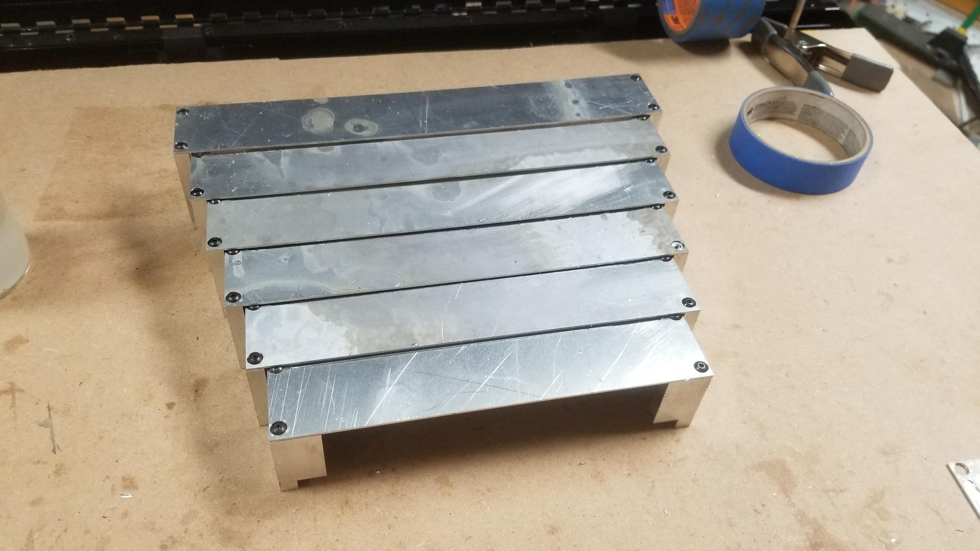
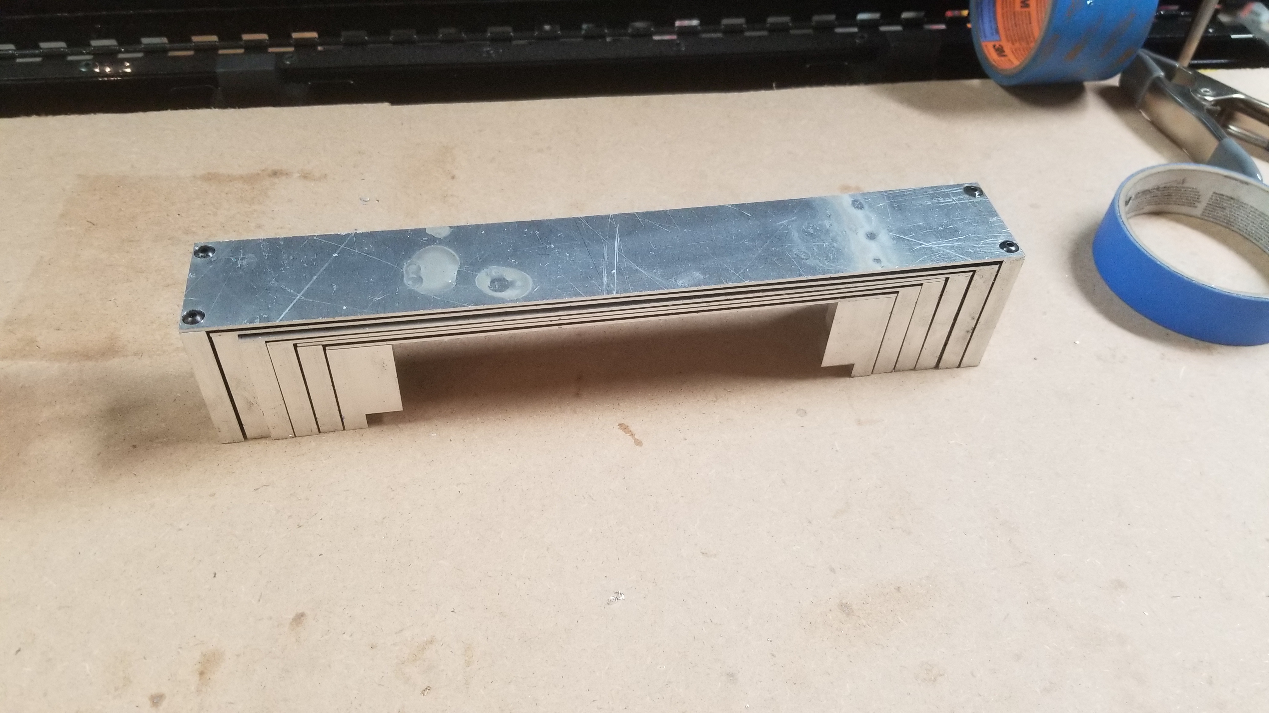
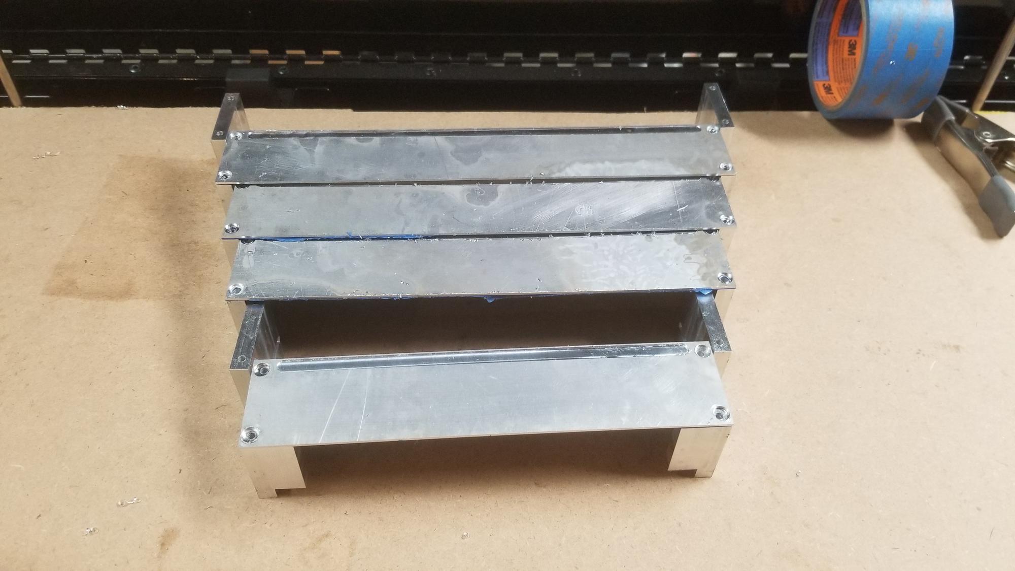
Here they are in all their assembled glory.
qoONukp.jpg


QDnStI1.jpg


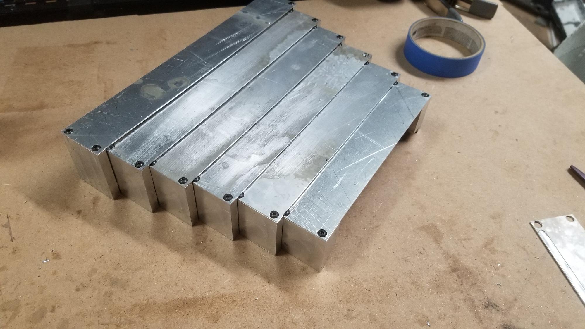
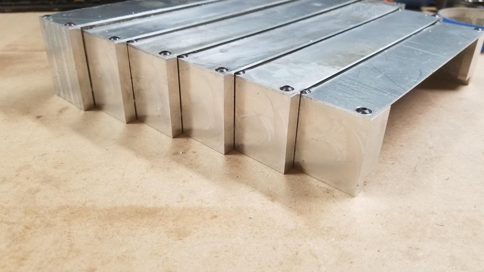
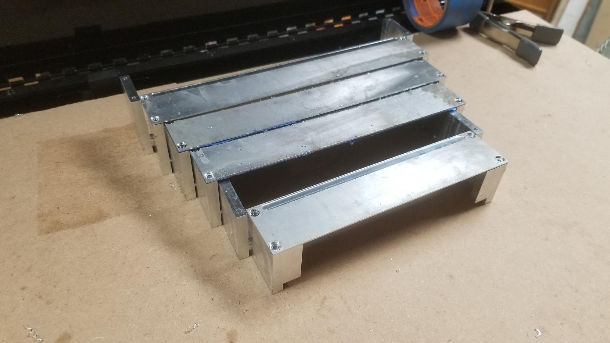
You can see the slight clearance between the segments here. Once I put the .025" adhesive rubber strips along the left side, that will be filled and should be kept uniform.
vrxpX5x.jpg


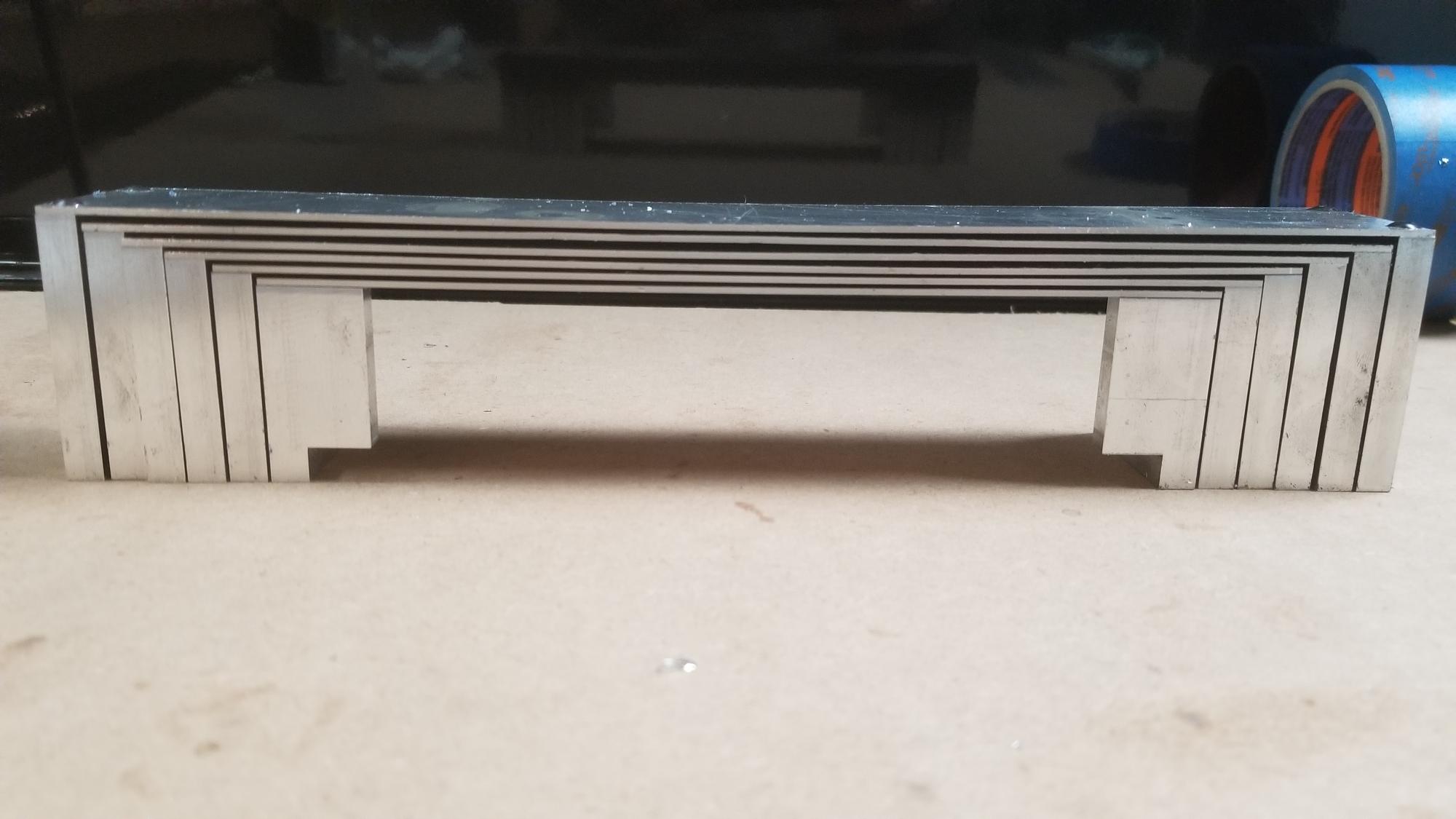
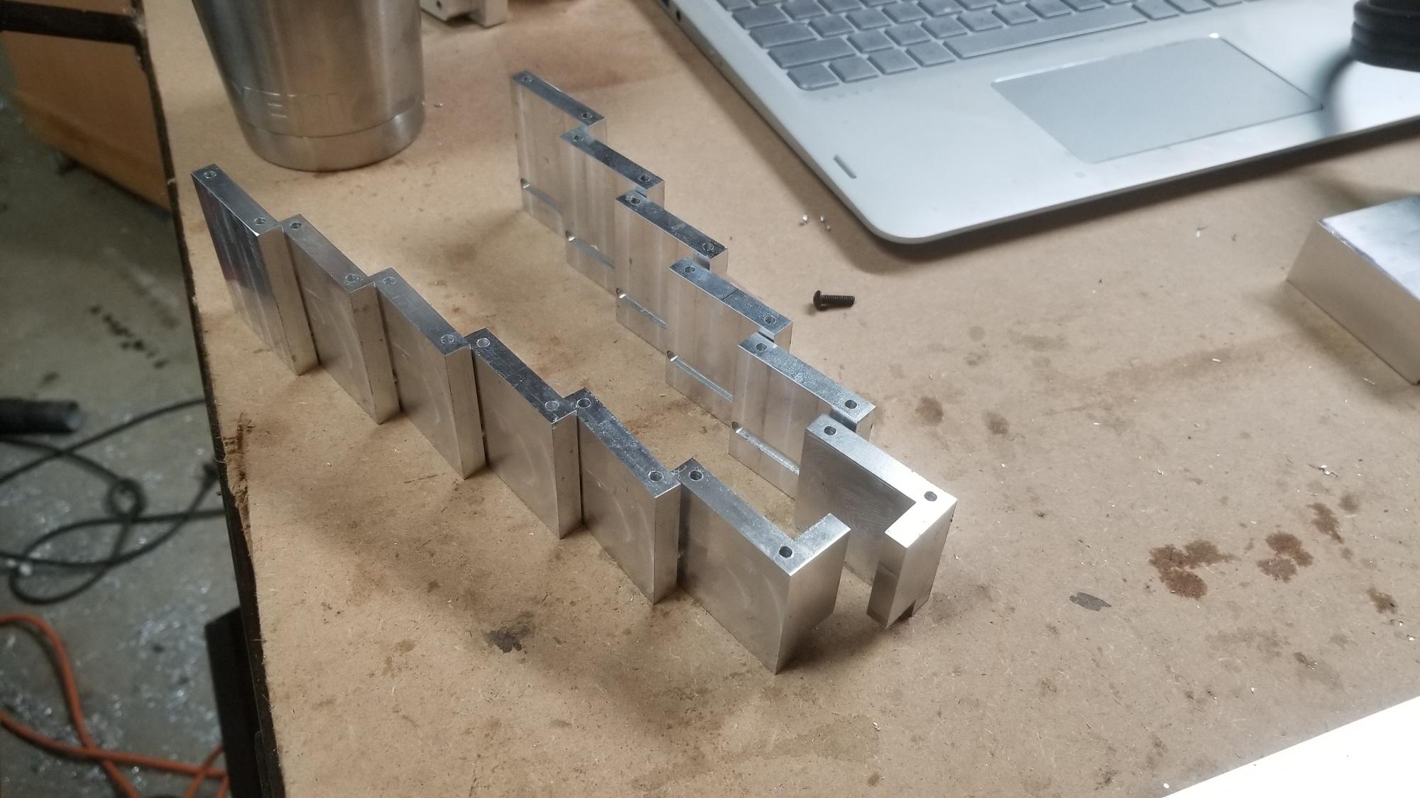
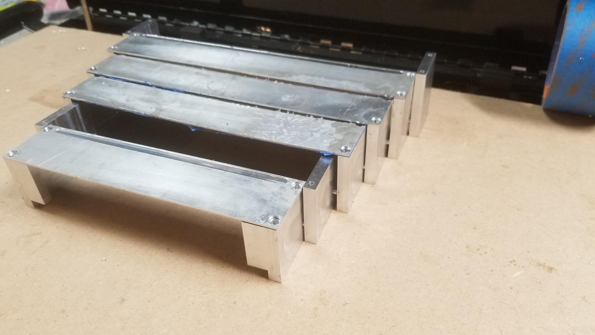
Here they are collapsed. You can see the sheets bowing slightly downward on a few of them. This creates the slightly larger gap between a few sheets. You might also notice the topmost ones have a slightly larger gap than the rest of the sheets. That would be because someone wasn't careful enough when he modeled it and made that gap too large...
FtnU1QJ.jpg


F0u1bjL.jpg


I am thinking I will sand the sheets to a brushed finish, maybe around 800 grit sandpaper. I don't want to make them shiny and then have them look rough as soon as a chip scratches them, but I also think they will wear better with a surface that slides easier.

One step closer to getting this machine the way I want it! It will soon be time to wrestle with the new electronics set up. I am looking into building a new PC to control it. I want to get rid of the big ol computer that has to sit next to the machine. Hopefully something with slightly better performance that I can fit in a smaller package. I was thinking of putting the control PC in the same box as the electronics, but the fear of noise interfering is pushing me to give it its own box.
 
Back
Top