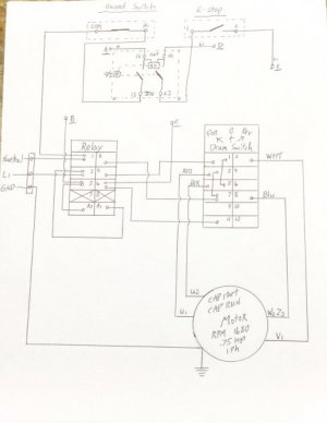
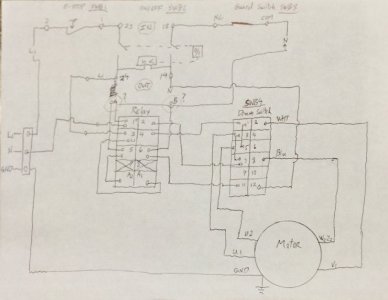
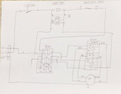
I noticed a discrepancy in your schematics:
(1) - (74) you had the Neutral wire leaving the bar, striking the contact and then heading over to the switches.
- Now in (75) you have the hot striking the contact and heading to the switches.
could you clarify and validate which?
(2) You need to verify your control circuitry. You drawing has both the neutral wire and your hot going up through your switches. It can't be this way unless there's something unique about those switches that i'm not familiar with. Usually use just the hot to break through control switches but you can use the nuetral wire to do, you'd just have to stay consistent with either one, going all the way through the control circuit. One or the other. I'd use the hot wire though just because it's easier to troubleshoot and you can grab a reading off a contact terminal on a switch to ground (anywhere on your machine housing). So just verify that nuetral wire you have drawn in on the right side of your control circuit on (top right of (75))
(3) Yes you'd need that A wire..that's your nuetral wire which completes the control circuit to A2 on your relay and makes the electromagnetic contact pull in because of coil. I don't think however that it needs to go up through anything other than just be terminated on A2 from your power supply entry point, which appears you have a terminal strip there.
A2 is typically wired for the nuetral and A1 for the Hot wire, verify your setup/ compared to your drawing.
So the way the control circuit works is, to have a complete circuit (one end of the coil -found inside your relay- is bonded to the nuetral whereas the other end is just sitting there idle awaiting for the hot to strike A1, which is the other end of the coil, thereby pulling in the contact.
The hot wire should go through an off switch first (which are Normally Closed) _-You do have momentary simple push button on and off switches, correct? --
then the hot leaves the off switch and goes through the Normally Open (On) switch. There is usually a set of auxillary holding contacts on the side of most motor control contactors, which continue to hold the control circuit complete, until the OFF switch is hit. I'm trying to determine based off your drawing how your setup does that after the ON switch is hit.


