2015 POTD Thread Archive

1983.

It's getting some major work done.


:)

I'm in the process of adding a 2002 royal star transmission gear set, vmax rear differential. VMax heads and vboost manifolds.

It's getting coil over plugs and digital ignition.

I'm ditching the old bias ply tires and putting 17" radial tire rims on it. Thats the reason for the green rear rim off a zx7r (modified to hold the spline drive for the shaft) and a 2006 r6 front rim. The wheel swap is the main reason I built the laser alignment jig (needs swingarm work to fit the 180/70r17 rear tire/rim).

Cartridge emulators for the front forks and I'm still working on what to do with the rear. I was working on a zg1400 shock, but I don't think that is going to work out (too long).

R6 monoblock calipers are also going on.

It's getting the later style side paniers in the photo, since they have more capacity than the 83-85 ones.

I'm also chucking on a set of r1 mufflers, mostly because they look kinda cool sticking out under the bags:

C1C3EDEE-43EF-48E6-9B04-CE5D72731BFE_zpsedsmalxo.jpg

I'm thinking of making it sort of a "bagger" for around town use:

Sort of a "honda f6b" concept. Low enough sheild to get a good blast of wind in the face around town (gets pretty warm behind the tall shield at low speeds) and put the top trunk and tall windshield back on for long distance rides. Bagger like the above pic is easy to do. I'll just build a second seat to bolt on and off with the small rear duck tail on it.

Lots of work done, lots of work to go....

:)

I like... Those pipes do look the biz :)

With the VMax parts, you're really going to annoy the Hardly-Ridables...

I have a VMax, did the wheel conversion (Diversion 900 rear with a 150-70/17 Battlax tyre, Thundercat 600 front and 120-70/17 Battlax), it almost corners like a motorbike...
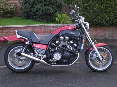
DSCN0047scaled.jpg

Also lowers it a touch, good for those of us with Dachshund Syndrome!

The front end conversion needed a little "machining" off the lefthand fork bottom to centre the rim ( left off the righthand spindle spacer and fitted wheel and spindle with the speedo drive in place then measured brake bosses to rim both sides, angle-ground/blued the speedo drive face/filed-to-flat-and-square until it centred) and a turning down of the spacer on the righthand side, the rear end needs a new spindle and the VMax dustshield grafted to the Divvy wheel and new holes drilled to mount it (in the shield, not the wheel!).
Something I really like is that the Thundercat and Divvy wheels are a really good match :)

Re calipers, I was lucky to find some YZF400R-3TJ four-pots which bolted straight on (same bolt spacing etc., need a thick washer / thin spacer between fork and caliper), big improvement for not a lot of money, but not a common part!

Can I ask a favour, swingarm pivot to wheel spindle distance? I've been thinking about putting a Venture swingarm on my VMax to get a monoshock back end as a possible alternative to modding the original (lengthening and bracing, which would involve a lot of welding and making a longer drive shaft...) - I looked at the Diversion 900 rear end, but it's not significantly longer (uses the same bevel box though with different clearances, so may offer another choice of final-drive ratio? May be worth checking out the FJ1100 / 1200 / FJR too?).

I blew it up running-wot-I-brung, so some serious work required for summer or I'll be stuck with just the ZZR1100...

Dave H. (the other one)

C1C3EDEE-43EF-48E6-9B04-CE5D72731BFE_zpsedsmalxo.jpg

C1C3EDEE-43EF-48E6-9B04-CE5D72731BFE_zpsedsmalxo.jpg

C1C3EDEE-43EF-48E6-9B04-CE5D72731BFE_zpsedsmalxo.jpg

C1C3EDEE-43EF-48E6-9B04-CE5D72731BFE_zpsedsmalxo.jpg

C1C3EDEE-43EF-48E6-9B04-CE5D72731BFE_zpsedsmalxo.jpg
 
When the storm was still south of Downtown, the funnel was about 1/4 mile wide and making a bee line straight for my neighborhood. It was moving pretty fast, about 30 mph. It got unorganized on it sway further north, but powered up again and split in half. The worse parts went west and east of me and the one that went east developed that wedge tornado.

Lots of houses got torn up and so far about 5 people have been found killed.

Glad you didn't get caught up in that Franko. We followed it on the Weather Channel last night. Crazy weather patterns the last several years.
 
extropic
Jems or stones are mounted to a dob. The dob then fits into a machine thats used to cut the facets.
I believe they are called "dops"
Dob is the shortened version of "Dobsonion" a type of telescope construction designed by John Dobson.
 
I'd heard them called dop sticks, and they (the ones I'd heard about were just sticks, pieces of wood) with a dab of sealing wax on the end.
 
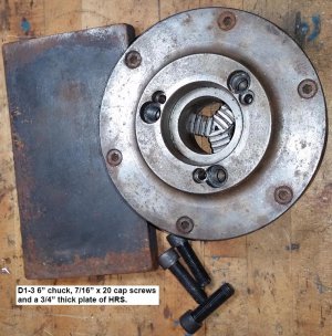
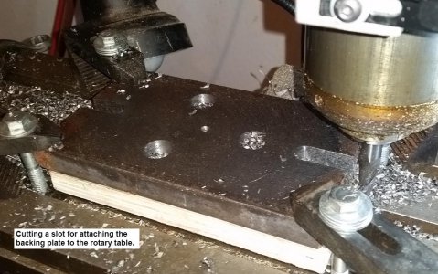
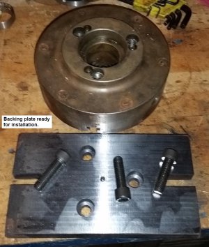
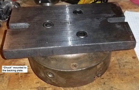
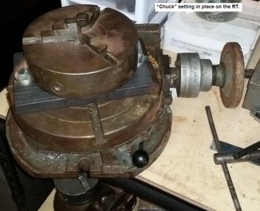
Got some shop time after Christmas clean up to FINALLY work on making a plate to mount a 6” 3-jaw chuck to my 9” rotary table. Used a piece of ¾” thick HRS for the base. The chuck has a D1-3 mount. Gotta love the web as a quick search showed the radius/diameter of the 3-hole pattern is 1.391”/2.782”.

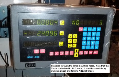
My Jet mill has an mTech DRO from TPAC tools (www.tpactools.com). I used the PCD function (no idea what the acronym is) for positioning holes on a circle and/or radius. In this case, I found the center of the plate and selected PCD on the readout. Inputs are circle center, diameter, number of holes, starting angle and ending angle.

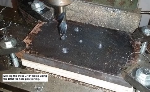
For my project, the table was already at the circle center so the ENT(er) key was pressed. Diameter was 2.782, number of holes was 3 (see note below . . .), start angle was 0, end angle was 360. At that point the DRO told me to move to 0 on the X, +1.391 on the Y for the first hole. Since this was my first time using the DRO PCD function I started with a block of wood. I moved the table to 0, 0 and drilled a hole. The down arrow on the DRO moves to the next hole which indicated #2 hole at 0 on the X and -1.391 on the Y. Huh, that’s a hole 180 deg. from the first one, not 120 degrees. Guess that’s why we prototype on a block of wood first instead of the final project!

My mistake was thinking of 3 holes on a 360 circle. The readout puts the 3 holes on a 360 circle at 0, 180, and 360. For attempt #2, the readout was told to position 4 holes on a 360 circle which placed them at 0, 120, 240 and 360. Naturally, hole #4 is on top of hole #1. Another input scheme could be 3 holes starting at 0 and ending at 240, but that would require me to do the math. In the future when using the PCD function on a full circle I’ll remember to add 1 to the number of holes to end up on the starting point.

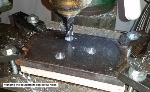
The D1-3 chuck uses 7/16” – 20 holes for attaching the backing plate. I had some appropriate socket head cap screws which would require countersunk holes about 0.425” deep in the backing plate so the heads wouldn’t hit the table. After drilling the 7/16” holes on the circle, I came back with a ¾” end mill for the countersunk holes. On my DRO, the PCD function disables the Z-axis (I have a 4-axis DRO with a glass slide on the Z, Vernier caliper on the quill). Fortunately the DRO switches between PDC mode and INC mode (so the Z-axis comes back on the display). HOWEVER, when going from INC back to PDC mode the coordinate system assumes you are at the center of the circle. So, when the table was positioned to hole 1 at X=0 and Y=+1.391, jumping back to PDC assumes that is the center of the circle. At that point I could have input the center as X=0, Y=-1.391 to hold to the original center, but I found it easier to just move the table back to 0,0 before jumping back to PCD mode for moving to the next hole for countersinking.

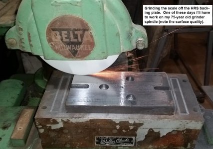
After countersinking the holes I cut a couple of ½” wide slots for attaching the plate to the rotary table. Next was using a 75-year old Delta Milwaukee grinder with some spindle wobble (see my surface finish) to clean up both sides of the plate. Voila, ready for my next project!

20151220_141602aaa.jpg 20151220_145931aaa.jpg 20151220_150237aaa.jpg 20151220_151417aaa.jpg 20151220_153424aaa.jpg 20151220_160854aaa.jpg 20151220_161126aaa.jpg 20151220_163411aaa.jpg 20151220_163917aaa.jpg
 
Last edited:
My project was hoping this thing didn't get me.
This was taken in Garland tonight, about 6 miles from my house and shop.
It is illuminated by power line flashes.

View attachment 117432

I just talked to my sister in Prosper. The closest anything came was about 40 minutes away from her. But a friend of hers had their house damaged, and father-in-law next door had the house destroyed.
 
I like... Those pipes do look the biz :)

With the VMax parts, you're really going to annoy the Hardly-Ridables...

I have a VMax, did the wheel conversion (Diversion 900 rear with a 150-70/17 Battlax tyre, Thundercat 600 front and 120-70/17 Battlax), it almost corners like a motorbike...

View attachment 117446

Also lowers it a touch, good for those of us with Dachshund Syndrome!

The front end conversion needed a little "machining" off the lefthand fork bottom to centre the rim ( left off the righthand spindle spacer and fitted wheel and spindle with the speedo drive in place then measured brake bosses to rim both sides, angle-ground/blued the speedo drive face/filed-to-flat-and-square until it centred) and a turning down of the spacer on the righthand side, the rear end needs a new spindle and the VMax dustshield grafted to the Divvy wheel and new holes drilled to mount it (in the shield, not the wheel!).
Something I really like is that the Thundercat and Divvy wheels are a really good match :)

Re calipers, I was lucky to find some YZF400R-3TJ four-pots which bolted straight on (same bolt spacing etc., need a thick washer / thin spacer between fork and caliper), big improvement for not a lot of money, but not a common part!

Can I ask a favour, swingarm pivot to wheel spindle distance? I've been thinking about putting a Venture swingarm on my VMax to get a monoshock back end as a possible alternative to modding the original (lengthening and bracing, which would involve a lot of welding and making a longer drive shaft...) - I looked at the Diversion 900 rear end, but it's not significantly longer (uses the same bevel box though with different clearances, so may offer another choice of final-drive ratio? May be worth checking out the FJ1100 / 1200 / FJR too?).

I blew it up running-wot-I-brung, so some serious work required for summer or I'll be stuck with just the ZZR1100...

Dave H. (the other one)
Looks good.

R1/r6 four piston monoblock calipe s are a dime a dozen on this side of the pond. They bolt right on to the 86+ Venture fork (I think its the same for later year vmaxes). My Venture is getting a set of 86 fork lowers since I have to pull them apart to modify the damper rods and install the emulators.

I've got a couple swingarms out in the shop.

Gimme a couple ticks and I'll see what I can find for you.

Be aware that the fuel tank placement on the Venture limits what shocks I can use, its right over the shock mount. Not sure how a VMax tank is minutes other than its under seat like the Venture.

Also, the rear shock on a Venture is right where the rear exhaust/collector box is on a VMax. Its the reason I have to custom make an exhaust isnted of just bolting up a vmax set. It may work if you have a 4 into 1. Only way to know is to try I guess.

I thought about going the diversion rear wheel, but its impossible to find one at a decent price and reasonable shipping costs from Europe to NA. I just ended up building my own wheel like Kosman engineering does. It also let me pic a wheel that was affordable since I was going to hack it up anyways. The 3 spoke rear doesn't match the 6 spoke r6 front, but that wasn't important to me either since its going to be buried under the luggage.

:)
 
Last edited:
Just waiting on my bar of 7075 to make the body, it's apparent to me that alignment will have to be done in two planes, a jack screw type setting for axial runout and 4 set screw for radial. I may have to remake the spider...
View attachment 117439 View attachment 117440
Chevy, Coming together! You are going push me into completing mine.

I think you will only have to do a radial runout adjustment unless you are really out of whack. The object is to get the center of the ball on the spindle axis and the radial adjustment should do that. The stylus shaft doesn't have to be coincident with the spindle axis.

Bob
 
I know but I like things to be straight square and parallel, it would be difficult for me to see the shaft at an angle and not do something about it. We'll see how it looks
 
Back
Top