2020 POTD Thread Archive

Yesterday's project was building a top nut lever for my QCTP. I had to build everything from scratch, including the t-slot nut and bolt. The original was metric and I didn't have the right tap.
Everything was made from stainless steel and I can tell you it was a real pain to tap the threads in the top nut. I really need to invest in a good, smaller internal threading bar for projects like this. I used a recessed brass washer in between the nut and QCTP to minimize wear. I will build matching knobs for the handles, I just ran out of time today.
UA22hGx.jpg

xF3mHn7.jpg

bPbbAQm.jpg


I didn't care for it being so tall so today I shortened it by 1/2" and clocked the handle back a little so it's in a better position for me. Now I just need to polish up the flats again and build new knobs.

8UHFSJo.jpg

Looks good @Lonnie, I have the same tool post and I’m always looking for the wrench to change the angle.
Curious about the small hole in the T-nut. Is that for a set screw?


Sent from my iPhone using Tapatalk
 
Looks good @Lonnie, I have the same tool post and I’m always looking for the wrench to change the angle.
Curious about the small hole in the T-nut. Is that for a set screw?


Sent from my iPhone using Tapatalk
Yes, there are actually 2 set screws in it, kitty corner from each other. I just duplicated what the lathe originally came with.
 
IMG_20200412_160941.jpg

Well. That turned out better than I had any right to expect from cold blue. I ordered Oxpho-blue from Amazon. While I was waiting for it, I started looking around for tips and found one guy mentioning that he found instructions for a competing product that used the same chemicals. It was to dilute the blueing component 1:9 in water, I used distilled, and soak the part. I decided to give it a go and I'm happy with the results. It takes a couple of minutes per dip to react fully. I washed them in water, lightly burnished with steel wool, and soaked again. Then rinsed for a couple of minutes in running water to make sure the chemicals were removed. Then dried and coated in way oil for 24 hours. The pic is just after wiping off the excess oil with paper towels.

Now I'm going to clean the oil out of the threads and loctite the studs in. I got most of the oil out with compressed air. I made a nice mist of atomized oil in the shop. Probably nice when it settles on the mill, maybe not so much the floor...
 
I’m in the middle of the build of a 32” diameter exhaust stack damper for a 1200 hp boiler
 
POTD was a refinement to the Tormach enclosure. The front doors have sliding panels so half of the mill is quickly accessible. The doors are both hinged so by pulling a stop pin they can swing open and give access to the full mill. I'd made bushings that are in the base and drilled holes up through the bushings through the swing door tubing for a locking pin. It worked great, but looked unfinished with a couple of holes in the tubing. Opened up the holes in the tubing and Loctited in a couple of stainless steel bushings for a more finished look.


Swing doors are held in place with a couple of pins. The pins went through drilled holes in the swing door tubing, but just looked unfinished to me.
20200405_113641.jpg


Made some 303 stainless bushings for the tubing to dress out the doors better.
20200410_143753.jpg

20200410_143710.jpg


I didn't take any photos of the operations as there are too many posts from me showing making bushings already. . . . Simple lathe job of facing, center drilling, drilling a clearance hole, parting and facing the parted end. The only "tricky" thing I ran into was alignment of the upper and lower bushings.

The door tubing had been drilled through with an "F" drill (0.257" hole) for clearance for the 1/4" pins. These were opened up to 3/8" holes for the bushings. Well, the pins were REALLY tight. The door bushings are about 1.25" long, so a bit of a challenge to align two of these perfectly on center and in line with each other. I ended up drilling out about 1.125" of the upper bushing for more pin clearance. In use, just a washer thickness of tight engagement is needed to align the doors. I also opened up the upper tubing holes a bit for some wiggle room, think I ended up using a "H" or "I" drill. Set the upper bushings in place with some wide-gap Loctite on the OD, pinned the doors to the base and let the Loctite set up. Works really well, pins in place make for a solid door and they easily pull for swinging the doors open.

Thanks for looking, Bruce
 
POTD was more Tormach enclosure work. The mill came with a machine arm support bolted to the control panel. That'd be inside of the enclosure so moved the attachment to outside of the mill.

Plan was to reuse what I could. Tormach sells a remote arm for the monitor, keyboard, mouse and job shuttle for $325, but went the POTD route instead.

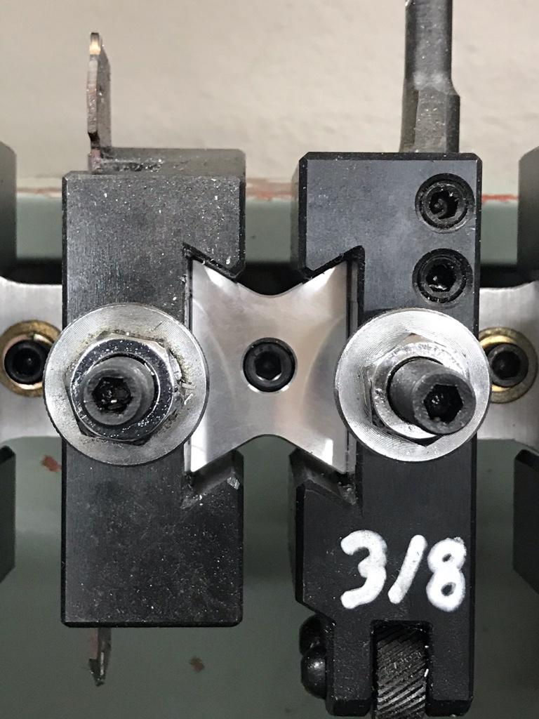
I mounted the cast iron arm base to the mill base with 3/8" cap screws. Set the base in place, marked one hole with a transfer punch, drilled and bolted one hole. Swung the base in place, transfer punched the opposite corner hole and repeated. Once the base was held with two screws, transfer punched/drilled the other two holes.

The existing arms mount with what mic'd as very close to 14 mm diameter pins (0.549"). The pins go through bushing plates screwed to the tubular steel arms. My plan was to mount the stock arm to the arm base and make a vertical extension tube from some 1" x 1/8" wall square tubing. The extension tube would have plates welded to each end which in turn would be bolted to new pivoting disks.


Cut the 1/8" tubing to length and squared up the ends on the Bridgeport
20200411_111829.jpg


Chucked up some 2 1/4" mystery steel; faced, center drilled, drilled a 3/8" hole and band sawed off 7/16" slabs. Went back to the lathe after each cut for re-facing so one surface was flat.
20200411_115248.jpg20200411_115404.jpg
20200411_115703.jpg20200411_122311.jpg


Used a couple of adjustable parallels on the face of the lathe chuck to set the disks in place for facing. Yet another POTD will be to make an adjustable spider. . .
20200411_125839.jpg20200411_125848.jpg
20200411_131328.jpg


Made four 3/8" thick by 2 1/4" disks. Two would be tapped, two drilled/countersunk. Started with the tapped ones.


Bolted two disks together and found center with a laser center finder. I'm able to hit within about 0.005" with the laser which was "good enough". Spot drilled, tap drilled and tapped both disks. I used the PCD function on the mill's DRO to locate the holes. Not necessary as the X, Y were Zero and the offset, but it's nice to step through the holes and go to 0,0.
20200411_135509.jpg20200411_140304.jpg
20200411_141616.jpg20200411_141847.jpg
20200411_142642.jpg


Plates that go on either end of the extension tube were done next. Same gig here, located them on the mill with the laser, spot drilled, drilled 3/8" through holes, countersunk with a 9/16" end mill, and milled an 1/8" pocket for the 1" tubing to set in.


I have a couple of sets of countersinks for 3/8" cap screws, but they create quite a bit of clearance. The center hole mic'd at something like 0.430" and the head clearance was something like 0.625". Went with the "trust the DRO" approach which meant having to hold better than 0.005" tolerance (spoiler alert, worked out fine).
20200411_143544.jpg20200411_144200.jpg
20200411_145756.jpg20200411_150724.jpg
20200411_153343.jpg

Test fit a chunk of tubing. Didn't show it but clamped the two plates on either end of the extension tube and TIG welded the assembly.
20200411_153416.jpg


Made some thrust washers out of Delrin.


Faced, clearance hole drilled and parted.
20200412_120547.jpg20200412_120755.jpg20200412_121122.jpg


Next were the clinch/captive pins. The stock one was the wrong length (could have been modified), but I needed an additional one anyhow so made two. Chucked up some 3/4" CRS, faced, center drilled, turned between center and cut an E-clip groove. Then polished it the way I was taught; cover the ways with a towel, Emery cloth over a flat surface like a file.


20200412_121908.jpg20200412_122018.jpg
20200412_124319.jpg20200412_125357.jpg
20200412_124830.jpg


Gonna hit the 30 photo limit, so on to part 2.

Thanks for looking, Bruce
 
Last edited:
Part 2 of POTD, Tormach machine arm move. Here's a shot of the Tormach arm. One advantage of their design is the height is adjustable.


Capture.JPG


The attaching disks are a pretty tight clearance to the clinch pins. I mic'd them at around 0.002" on the Tormach parts. Chucked up the threaded disks for boring the central hole to size. Again, used parallels on the chuck face to get the disks flat.


Set a disk in place with a couple of parallels. Drilled a 1/2" hole prior to boring (guess I didn't shoot any photos of the boring. . .). Target was 0.550" for 0.001" clearance to the clinch pins.
20200412_130432.jpg20200412_130651.jpg
20200412_131255.jpg20200412_131404.jpg


Lower support arm parts in place. Clinch pin goes through one of the tapped disks, Delrin thrust washer between the tapped disk and machine arm bushing. Second photo is with the extension tube bolted to the lower disk.
20200412_131542.jpg20200412_152202.jpg


Upper mount parts in place. Clinch pin goes through a Delrin thrust washer, the table support, a second Delrin washer and the second tapped plate. An E-clip holds it all together, then the assembly is bolted to the top plate of the extension tube.
20200412_152249.jpg


Test fit everything together before painting with some Rustoleum. Pretty happy with the final result. Arm is very stable and easily swings out of the way. I didn't show it, but dressed up all of the cables too. Made a sheet stainless steel bracket which holds a USB hub in place. There's a loop at the bottom of the bracket (repurposed auto cargo loop) for hanging the USB cables for the monitor, keyboard, jog shuttle, mouse, and aux USB for a jump drive.


20200413_143943.jpg
20200413_144010.jpg
20200413_155857.jpg


Thanks for looking, Bruce
 
Last edited:
I made a back to back bracket for my lathe tool rack. My usual 1” angle brackets wind up taking 2.25” back to back. This block is 1.2” and allows me to squeeze one more tool on the rack.


That's a nice looking mount! I am going to need to do something like that here soon. My current lack of organization is taking way too much space. :)
 
Back
Top