POTD was getting a new a me DoAll 16” band saw up and running. I have a Craftsman 12” wood cutting band saw and a Harbor Freight 7 x 12 horizontal/vertical band saw. I’ve gravitated from mainly a woodworker to more a metal worker over the years and wanted a vertical band saw for both wood and metal. I looked hard at a DoAll 20”, but it was a little large for my shop. I found a 1948 DoAll ML saw about 60 miles away for $1000 and was a new owner between Christmas and New Year’s.
Yeah, really rushed into the project to get it up and running! First step was getting it movable which was done with a Grizzly mobile base. I shored up a couple of areas with 3/8” thick bar stock as the saw’s foot print is not a rectangle.
Bought a 1300 lbs. rated mobile base from Grizzly. I had to throw some bar stock under the saw to support the back side as the mobile base just has support pads in the corners.


Next was the wiring. I went with a static phase converter as the saw runs on a 3/4 HP 3-phase motor. I have a Bridgeport that’s 3-phase also, bought it years ago with a static phase converter already in place. I’ve not had any issues with just 2/3-power on the BP, so went the same route on the saw.
My plan was to wire 220 single phase to a DPDT ON/OFF switch and run the hot side of the switch to the phase convertor. An aluminum bracket was made to attach a switch box to the side of the saw. The previous owner had screwed a bracket to the side of the saw to hang the wiring. My bracket picked up the same holes.
Used a piece of 1/2" aluminum for a switch bracket. Drilled the corners out.

Milled away the center

Drilled/tapped some mounting holes

DPDT switch and switch cover screw to the aluminum plate which in turn screws to the electrical box

Mounted the 1/2" plate to some 1/4" plate. The 1/4" plate would be screwed to the side of the saw

The previous owner made a bracket for the saw's power cord. I used the same holes for the switch bracket.

Start/Stop switch in place

The phase converter was mounted to the back side of the saw. I took a few “liberties” here as the saw was wired for 30A (#10 wire) because of the blade welder. The terminal block in the phase converter maxed at #12 wire, so I spliced #12 to the #10 instead of changing to a larger terminal block. The motor will only draw a couple of amps when running, so no issues there. The welder is a generic DoAll for 1/16” – 1” blades. My saw can only use up to a ½” blade, I’m thinking (hoping) that since I won’t be maxing out the welder, it should be fine. I welded up a bunch of short ½” pieces at the Medium setting and the wiring wasn’t even warm.
Screwed the phase converter to the back of the saw. Pretty simple wiring: 2 lines of 220 single phase in (plus ground), 3 lines of 220 three-phase out.


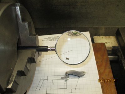
I still have a little work to do on it, but it runs great as is. My speed indicator (speedometer) needle shaft is broken. I’ll either turn a new shaft, or stick in a Hall-effect tachometer like the ones you see on many lathes on this site.
See the speed indicator needle at the bottom of the speedo?

Ended up the needle shaft is broken

I'll either try turning another shaft or just go with a Hall-effect tach (if anything at all)

Also, the power feed mechanism is mostly missing. I’ll probably make the parts as it’s more or less a piece of angle iron with 4 pulleys. Also, a length of cable and some roller chain. I do see a use for it as it pulls material into the blade instead of me pushing.
One lesson learned for those like me who fail to read manuals. The blade welder works great. Snip off a length, grind the ends flat, grind in a slight bevel, clamp them in place. Adjust the weld current, and pull down on the weld lever which cams the right-side piece of blade into the left for some filler metal at the weld. After welding, it’s best to anneal the blade which is done with the push of the Anneal button. Here was my problem.
The welder is turned on/off switch with a toggle switch. Turn the switch on and the blade grinder cranks up and the welder is live. I hit the Anneal button after welding and nothing happened. I thought about a quick work-around of just dialing the welder current to the minimum setting and give it a hit. Problem is, the right clamp moves to the left to jam the blade ends together during welding. Simple fix, loosen the right-side clamp so when the welder is energized, the clamp moves but the blade slips in the jaw. The clamp should have enough contact to complete the circuit.
For whatever reason, I hit the Anneal button with the welder OFF with the RH clamp loose and saw sparks. Go figure, turn the welder ON to grind/bevel the ends and weld the blade. Turn the welder OFF to Anneal the blade. I don’t know if this is how the welder is supposed to work, but at least it works. Maybe something with the static phase converter though I don’t see how. Look for some "What did you buy today" posts from me with bulk blade stock. Yeah, been shopping on eBay again!
Toggle switch above the grinding wheel turns the welder on. Stick the blade ends in the clamp blocks, set the pot to blade width and pull down on the weld lever above the blade clamps. That energizes the welder and pulls the RH clamp toward the LH for some filler metal. The Red button is for Annealing the blade which works when the welder is turned off (?!?!)

As she sits!

The 16" DoAll is headed to the Craftsman 12" saw's home

Thanks for looking.
Bruce


 . Couple of months ago i called about a local ad, tire shop selling off used tires in bulk, and happened to be the first to get there and bought many rims and wheels as spares for the little russian 4x4. The other black ones are from a Citroen C5 i had them on the shelf i'll refurb them as well to have them ready to go or i may just write an ad and get rid of them all, with the bad roads around here rims are in high demand.