An Electronic Leadscrew Controller using a Pi Pico

Due to my laziness, and also since the information should be posted in the right place, I posted on the PJRC forum asking about the 3.2" display. Paul (the owner) put up a mechanical drawing for the top view of the PCB. He just resells these, so that is what he has. The dimensions confirm my measurements, which had me puzzled initially. Metric drawings with a few odd dimensions, so guessing that the dimensions were nice even metric values would have been wrong. He posted it under his display web page at 320x240 display. I think the only missing major dimension is the hole size, which appears to be a scant 2 mm. By this I mean, a 2 mm screw can be screwed into the hole. Hope this helps. Here's a picture of it.
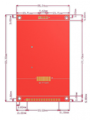
display_ili9341_touch32_drawing.png
 
Thanks, I didn't see your post until I posted mine. Looks like you found them a few minutes before I did. I was searching their forum (didn't see your post there) and then rechecked their web page and noticed the dimensions were larger on the second image, earlier I had thought it was a different view of the 2.8.

You mentioned that a 2mm screw barely fit, so I made the mounting holes 2mm. With 3D printing the holes tend a tiny bit small so a 2mm screw will bite plastic on a 2mm hole. Not too strong but adequate for this. I like the heatset brass inserts for more permanent use.
There were no dimensions posted on the PJRC site for this 3.2" display, until I asked Paul for them. I asked last night.

Today, Paul put the drawing online, in response to my request. Paul, one of the co-owners of PJRC, (Paul J Stoffregen, posting as PaulStoffregen), is quite responsive to reasonable technical requests. I have found the PJRC forum is very technical and quite helpful. I post under a different name there, making an feeble attempt at online anonymity.
OK. I found them this morning on the PJRC website product page and thought I had missed or dismissed them earlier. I updated the CAD and posted, and then your post showed up in my browser. I must have read your post too quickly and missed those details. Thanks again for shaking the tree and prompting Paul to post that. I was quite surprised it wasn't there in the first place, Paul is generally quite thorough.

Paul has always done quality work. I have found that his code and hardware have been excellent. I made a number of projects with the Teensy2 long before there were 3's and 4's. I was thinking about sending him a request or posting on the forum this morning, but as far as I can tell I don't have a login on his forum. I thought I had posted on the forum at some point in the past but at least so far haven't found a record of the credentials. I generally find what I need by searching, experimenting and measuring.
 
Last edited:
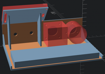
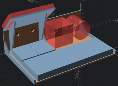
Was wondering if I could fit a little more breadboard space in, managed to get a couple of the smaller solderless boards to fit without making it larger. If a second Pico is used for pulse generation things might get a little tight on the one board. Currently under 9 hours and four dollars worth of plastic to print. Experimenting with extruded polygons for the support ribs. Probably should have something to anchor the 12 volt power cable. Anything else missing?

1653931459932.png
 
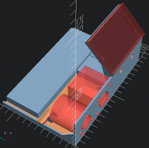
Added a little block to strain relieve offboard wires such as power. Due to the printing orientation planned (front panel down) I had to add gussets and a sacrificial membrane to avoid needing supports while printing. Two curved cable tie slots are printed into the block and the top is slightly curved where the wires will sit. I thought about a terminal block but there isn't a lot of space for that, and it doesn't completely solve the strain relief problem anyway.

1653936878441.png
 
Seems like you are having fun with that... Doesn't need to be perfect, as it is just a tool to make things a little easier.

I'm debugging the display stuff in a kind of a bodge of stuff. Don't feel, that fixturing what I have helps me get that done. When my NEMA-24 comes in this coming, I will need a better set up.
 
You are right. I'm just enjoying the CAD, and trying some things. Unfortunately once printed there will be more ideas, but this is a bit much to print several times. So I'm trying to avoid that and think of things ahead of time.
 
Last edited:
Having a good test setup is important for continued development and support. I don't want to be debugging on the lathe. So will probably want to keep the test setup working at some level. I don't have two Omron encoders so I might substitute some other cheap encoder once the Omron has been mounted to the lathe, or just use the pulse generator for testing. I can print an adapter to mount a physically smaller encoder in the Omron's place, or a perhaps a pot to control the pulse generator.
 
Back
Top