-
Welcome back Guest! Did you know you can mentor other members here at H-M? If not, please check out our Relaunch of Hobby Machinist Mentoring Program!
You are using an out of date browser. It may not display this or other websites correctly.
You should upgrade or use an alternative browser.
You should upgrade or use an alternative browser.
An Electronic Leadscrew Controller using a Pi Pico
- Thread starter AlanB
- Start date
- Joined
- Dec 18, 2019
- Messages
- 6,470
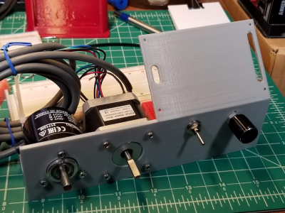
Flaw or not, looks pretty good. Way nicer than my setup.
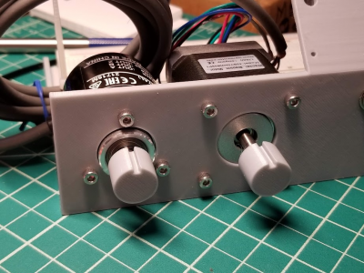
Thanks. I forgot how long that encoder cable is. Going to need a bit of cable management. The flaw is I missed the anti-rotation tab on the knob encoder. I'll have to drill a hole for that, not going to reprint unless something more significant is found.
My bench is covered with test setups that are so fragile I can't readily move them. I'd like to improve on that going forward.
My bench is covered with test setups that are so fragile I can't readily move them. I'd like to improve on that going forward.
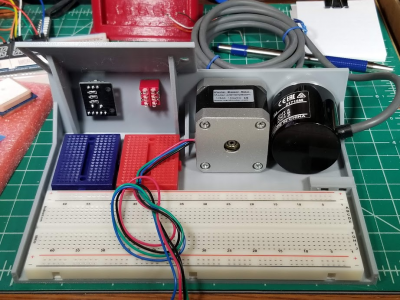
Drilled the hole for the encoder knob locating tab, dug up some M3 screws. Everything fits so far. The cord anchor came in handy for the encoder cable. I anchored the breadboards just in the corners, might want to take them off at some point. Hopefully the display fits, otherwise I'll be removing the breadboards much sooner than planned.


- Joined
- Dec 18, 2019
- Messages
- 6,470
Depending on how vigorously you spin the encoder, your setup may twist due to the motor torque. Just got my NEMA-24 closed loop stepper working and it's torquey. Will jump pretty far if you spin the encoder quickly, especially at full current. Just an advisory warning. You may want to reinforce parts with metal. You wouldn't want a pretzel on first use.
Thanks for the heads-up.
I usually put a "C" clamp (to the table) on loose motors when powering them (it's also good to put a ground wire, we had a shock incident at work without a ground wire). The 2HP treadmill motor I set up for the spindle on my previous lathe was quite torquey, and round so hard to restrain and really wanted to move. One had to be careful with that. A NEMA24 has a lot of rotor mass to work against. These NEMA 17's are commonly used on 3D printers and mounted with plastic mounts, and my plan is to run reduced current so it doesn't really have much heating which will also reduce the torque. But I will keep an eye on it. Probably more of a risk when using a pulse generator, too. Another risk is heating the motor and softening the plastic mount. Since I don't have a load (or a high speed requirement) there's little reason to run the current very high.
I usually put a "C" clamp (to the table) on loose motors when powering them (it's also good to put a ground wire, we had a shock incident at work without a ground wire). The 2HP treadmill motor I set up for the spindle on my previous lathe was quite torquey, and round so hard to restrain and really wanted to move. One had to be careful with that. A NEMA24 has a lot of rotor mass to work against. These NEMA 17's are commonly used on 3D printers and mounted with plastic mounts, and my plan is to run reduced current so it doesn't really have much heating which will also reduce the torque. But I will keep an eye on it. Probably more of a risk when using a pulse generator, too. Another risk is heating the motor and softening the plastic mount. Since I don't have a load (or a high speed requirement) there's little reason to run the current very high.
Last edited:
The PJRC display order arrived, very prompt (they are far quicker and closer than Adafruit). That's the good news. Now for the not so good news.
So far I found 3 errors, and will want to reprint the chassis. The slots are not offset properly, the display is upside down (sd card points down), and the screws are much too small. 3mm fit the holes, and I had used 2mm. There is often a feature in the library to flip the display over, however I have found in the past that the Pico version often doesn't support this feature (it may in the future, or already, I haven't checked). The documentation says the SD card doesn't work without hardware hacks, and may still not work, so I could ignore that, but if the display won't flip in the library that would be a problem. But the slots are offset wrong and that is a problem. I'll get to find out how hard it is to remove the breadboards. I only removed the paper covering on the corners, so they are only stuck in small areas. Perhaps cooling it in the freezer for a few minutes would make it easier to remove. Have to test it. Since I don't care about the existing plastic I can cut it up if that helps. I don't have much time to work on it today.
So far I found 3 errors, and will want to reprint the chassis. The slots are not offset properly, the display is upside down (sd card points down), and the screws are much too small. 3mm fit the holes, and I had used 2mm. There is often a feature in the library to flip the display over, however I have found in the past that the Pico version often doesn't support this feature (it may in the future, or already, I haven't checked). The documentation says the SD card doesn't work without hardware hacks, and may still not work, so I could ignore that, but if the display won't flip in the library that would be a problem. But the slots are offset wrong and that is a problem. I'll get to find out how hard it is to remove the breadboards. I only removed the paper covering on the corners, so they are only stuck in small areas. Perhaps cooling it in the freezer for a few minutes would make it easier to remove. Have to test it. Since I don't care about the existing plastic I can cut it up if that helps. I don't have much time to work on it today.
- Joined
- Dec 18, 2019
- Messages
- 6,470
Supposedly ILI9341_t3 works with all Arduino architectures. This library was altered by PJ Stoffrogen. Couldn't tell you if it works with a Pico though, but the Arduino Reference section says it too. https://www.arduino.cc/reference/en/libraries/ili9341_t3/. I know I have used the image rotate function, otherwise, I would have gone insane! BTW, there is also a rotation function for the touch display. And of course, the required rotation for the image and the touchscreen are different! There should be a sticker on the anti-static bag that the display came in, showing the table. For me, all I needed to use was tft.setRotation(3); ts.setRotation(1);The PJRC display order arrived, very prompt (they are far quicker and closer than Adafruit). That's the good news. Now for the not so good news.
So far I found 3 errors, and will want to reprint the chassis. The slots are not offset properly, the display is upside down (sd card points down), and the screws are much too small. 3mm fit the holes, and I had used 2mm. There is often a feature in the library to flip the display over, however I have found in the past that the Pico version often doesn't support this feature (it may in the future, or already, I haven't checked). The documentation says the SD card doesn't work without hardware hacks, and may still not work, so I could ignore that, but if the display won't flip in the library that would be a problem. But the slots are offset wrong and that is a problem. I'll get to find out how hard it is to remove the breadboards. I only removed the paper covering on the corners, so they are only stuck in small areas. Perhaps cooling it in the freezer for a few minutes would make it easier to remove. Have to test it. Since I don't care about the existing plastic I can cut it up if that helps. I don't have much time to work on it today.
Pity that you made the SD socket upside down.
I have never removed the adhesive backing on my breadboards. From what I can tell it is just double backed foam tape. I don't like using adhesives, if I can avoid it. The adhesives get gummy, and are hard to remove, or they fall off on me. I found some breadboards with screw holes in them, should I want to firmly tie them down. Think Adafruit has them, probably other places as well.
Of course, I don't trust solder-less breadboards for anything serious. The contacts aren't reliable enough. I attempted an analog design (7 pole active Chebychev filter) on one, and that was a mistake. Was constantly chasing my tail on that. Finally went to a soldered version, and everything became stable enough to debug.
I just reviewed the PJRC site, every view appears to have the long strip of pins on the right. The dimensional drawing/photo doesn't show the silkscreen or the SD card. It's very hard to get right when all the clues are unclear or backwards. I suspect that many applications want the SD card on the bottom. The silkscreen on the back is rightside up with the SD upward. The hole locations are correct, the sizing for the holes is missing. I did offset the pin clearance slots slightly wrong, due to some changes I made in the coordinates for the display which I didn't compensate properly for in the slots.
I thought about making the display panel a separate part. Could do that for the next version.
Sometime back I found optimized libraries for the Pico for this ILI9341. Other libraries are also said to work but much slower. I haven't looked into them in detail yet. There appear to be several to choose from.
This is the first time I've removed any backing from solderless breadboards, if I don't do something they'll be falling all over the place in this application, I only cut the corners of the backing so triangle shaped areas can adhere, about 1/2" on a side.. I just lifted them right out, it was not hard. So I'll make a few adjustments to the CAD and print another chassis. Looks like a spool of plastic could print 9 or 10 of these. Not a big commitment. Much less work than making something by hand.


