An Electronic Leadscrew Controller using a Pi Pico

I don't want to be debugging on the lathe.
You probably will be, despite your efforts, I know I will be. Making small changes and shuttling between setups doesn't sound appealing to me. There will be bugs that only show up on the lathe, trust me. Have started thinking about how to manage further debugging in the shop. Considering making a small stand up debug station.
 
Well, the switch and knob encoder arrived, so those holes are verified. The display order is fouled up because the bank closed their web processing account after someone tried to use some bad credit cards on their website. So that will delay things a bit.
 
Well, the switch and knob encoder arrived, so those holes are verified. The display order is fouled up because the bank closed their web processing account after someone tried to use some bad credit cards on their website. So that will delay things a bit.
Well that's unfortunate. Maybe the bank should have better SW to reject bogus cards? If they don't authorize, they should be rejected. Buggy software, we don't write code like that ;) . I'm sure it will get sorted out quickly.
 
They have essentially been dumped by the bank, and will have to find another bank to process their website. If it turns out to be too much of a delay I'll just go with the Adafruit unit, which is double the cost but has a working SD slot. PJRC are using direct PayPal payments as a stop-gap so that should work.
 
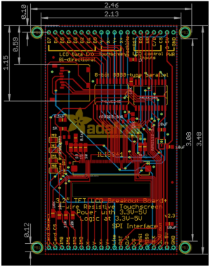
The Adafruit display dimensions are not easy to find either. I did not find them at Adafruit.

1654015121886.png
 
Unfortunately the Adafruit and PJRC 3.2" TFT displays aren't very compatible mounting-wise. Tricky to make a mount that works for both.
 
I have been designing circuits and writing micro-controller code since the early 1970's. I'm new to hobby machining though. I'm really interested in this project because is merges my skills with a great hobby. Clearly all those that have posted have a good appreciation for the problems involved as well as different ideas about how to proceed.

The Omron encoder is very interesting because of low cost, resolution, and RPM range. Are you planning on driving this encoder via a gear to leave the spindle tube open for stock? I would be interested in a similar encoder that would fit over my spindle tube.

There are literally 1000's of processors available. The Pico may be a bit overkill, but better that than under-powered. I favor Platform.io for an IDE for this type of work. You have all the Arduino code plus a more powerful development platform.

I'm waiting to see how this comes out.

Spajo
 
Welcome Spajo, good to see your comments here.

Early 70's about the only microcontroller available was the 4004. I did some projects with the 4004 and 4040 in about that time frame. It was fun trying to explain to the EE's at the small company how an assembler worked. ProLog had them hand-coding and typing in hex codes to a prom programmer, and they didn't know any better. Pretty soon they gave all the programming work to me and went back to their electronics. :)

I did a lot of projects with the AVR micros before Arduino came along. The Arduino environment did simplify things a bit. I use whatever is easy, haven't tried Platform IO yet. I'm not generally fond of big complex IDEs, I don't usually need the huge feature set and the next project may be something different and learning new IDEs is a distraction. But that's just me. The code should port and the real value is in the principles and techniques that work.

The bore on my PM-1228 lathe is 1.5" so I'm planning to drive the Omron from the gear on the spindle in some yet to be determined way. There are lots of examples of mounting Omron's on lathes already out there in various ELS and CNC projects. I haven't looked at encoders that could surround the entire spindle tube. I don't want to mod the lathe. I'd be interested in what you find and are thinking of doing there.

I did send the funds to PJRC for the display. We'll see if they ship quickly. Yes, they already added tracking info. They are quick.

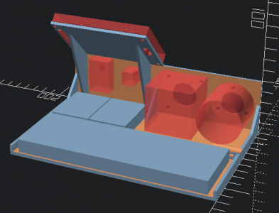
I made display mount CAD for both the PJRC and the Adafruit 3.2 TFT, but they overlap in a problematic way. Offsetting them enough to fix it might work, but it makes the display support wider.
 
Last edited:
Trying to accommodate both displays is not worth it here, the PJRC 3.2 TFTs are being shipped and are less expensive, and the Adafruit displays have so many pins the clearance slots weaken the panel if trying to support both. I have both in the CAD model but setup now so one has to be selected at a time. This is with the PJRC, and the knob and switch were detailed and moved a bit to fit better. I'll let this sit and see if any more ideas occur while waiting for the display. This may be a good base for future breadboard setups, it can be adapted to other projects and reprinted.

1654033683315.png
 
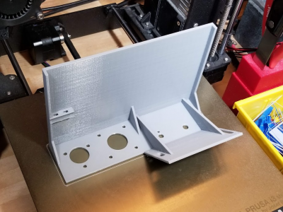
The Printer got busy last night.. Was planning to wait, but this way we'll have something to fit to.

1654091537244.png
 
Back
Top