Updates!
So here are some things I would have done differently. I may retro later, but I would need to buy another Z axis scale that I cut to fit the right side of my column.
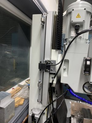
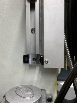
I installed the Z axis DRO scale on the right, and due to the Z axis crank handle casting, I had to cut the scale shorter to fit. I should have mounted this on the left handed side of the mill where I mounted the Z limit bracket, and mounted the limit bracket on the left as well, so the read head and the limit switch rode the same assembly. I could have an additional inch or so of travel in Z, specifically in lowering the head. IF this becomes a limitation, I will re-do the Z DRO, buy a new scale, and mount the scale, head, and powered limiters all on the left. There is no reason why the read head and limit switch cant be stacked on the left Side of the head.
View attachment 389177
View attachment 389178
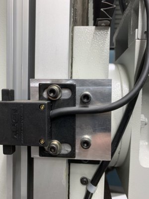
My Y axis placement worked fine here.
View attachment 389179
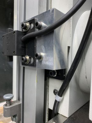
And for now I just put my X axis power feed switch here, and used 1 existing hole.
View attachment 389180
First parts in steel that I made aside from my lathe T-nut are these pieces I plan to wend to the lintel of my fireplace to suspend a wrought iron grate to. No need for a screen because its gas logs. I still need to set up my bench grinder and hit these with a scotchbrite wheel.
View attachment 389181