Beauty in The Beast: Webb 5BVK Barn Find/Conversion

Short update.
Been a while - as I have gotten side tracked on a lathe, here: https://www.hobby-machinist.com/threads/new-to-me-11-logan-920.93841/page-7#post-869233
Jim's DRO works a charm!
Install is some work - tight quarters - but I am happy with the outcome.
Have a slick solution for the quill (Z) but haven't fully executed the finish yet - so holding on that until I can share pretty pictures.

Excellent to have DRO operational.
Unfortunately - lathe is now in middle of garage as I re-org.
Looking forward to getting back to this project soon.
Lathe up and running will allow me to make screw extension/ add handles.IMG_3301.JPG
 

Attachments

  • IMG_3301.JPG
    IMG_3301.JPG
    3.4 MB · Views: 12
Been a while.
Was on my way to the gas station for cigarettes - and just kept driving... or something along those lines.
Actually - I went down a lathe rabbit hole - and when I got to the darkest deepest place - I saw a second hole - and took that one as well.
Happy to say, I'm back.
Quick recap in pictures.
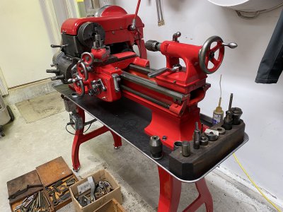
Bought this:
00T0T_8aA61oIQXJnz_0CI0t2_600x450.jpg
Turned it into this:

IMG_4008.JPG

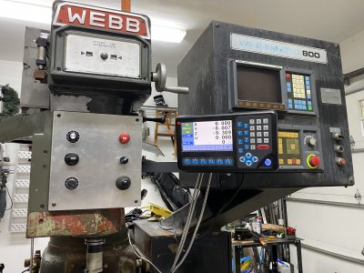
But then I discovered these existed:

img26.jpg

And this came available at a great price I couldn't say no to - so I said yes!
IMG_4426.JPG

Though it required that I buy two other mills - which I dutifully loaded up
IMG_4302.JPG

And sold before they even left my tailer.
IMG_4321.JPG
There was one point, about two weekends ago, where I owned three mills and two lathes all at once - and within 24 hours I was back down to my target one lathe one mill... Could hardly move for 2 days after all that loading and unloading.

Anyhow - having caught everyone up on the goings on - I've spent the last few days making parts and working with the machines.
Nothing like a project to really learn what's working - and what's not.

The mill is good - but has some issues I would like to address.
1. Table movement with my cheap DC power supply is ok - but spindle is inconsistent. Doesn't run well when I turn down the rheostat. Need that slow movement to be smooth. Considering something like this as a more powerful drive - but hesitant until I have a better long term plan.
Screen Shot 2021-09-21 at 11.53.54 PM.png
2. Though it's mostly minor - I HATE the big ass control box that hangs over the table. What a terrible idea. Makes my work dark as a cave - and is a constant hinderance to peering in to take readings. Not to mention its only a matter of time until the corner of that thing rips my scalp.
3. The tools stick in the spindle taper. I have to whack the draw bar with a mallet to knock them out.
4. (related I suspect) Their is some run out - about .0015 inside the spindle - and at least twice that when a tool is inserted. Picture below and some video. It looks to me like there is some galling - though not terrible - inside the spindle. Probably a few high spots causing me issues I suspect.
Picture is rather poor - but you can see some markings.
IMG_4486.JPG

Here is a video showing the run out.
Spindle:
Spindle:
Tool holder:

Looking for input on severity of spindle issue.
The non-self releasing factor has held me from rigging up the power draw bar unit I have - but perhaps that would do the job of pressing down hard enough on the draw bar to help remove the tool. Will test.

Let me know your thoughts on the value of having the spindle ground - have the name of a mobile guy that works this area. Braced for just how expensive that might be...

Thanks for taking the time to have a look.

-CM
 

Attachments

  • IMG_4195.JPG
    IMG_4195.JPG
    3.4 MB · Views: 9
The red one came out nice! Check out Four Ponds Shop on YouTube because he has already restored a Monarch and is restoring two others. He doesn't go into a lot of detail but he makes them look damn pretty.
 
Also love the Monarch. What is the spindle bore on those 10EE's?
 
Well - I am glad to see I am not the only one smitten by the Monarch.
Hooked by the Art Deco look - but blown away by how nice it is to use.
Extremely solid and precise - smooth.
Shaky picture on Ebay - no description - no response to questions - less than $3K.
On a whim - hit buy now.
Turns out to run nicely - and has a Sabina digital drive.
The seller was 80 - had used it for 30 years in garage as hobbyist - and just wasn't very good at posting pictures.
I helped him unload all his machinery - and he gave me a really nice deal.

Dan - I have been watching his series. He does a super nice job on finish and cleaning and bringing back to original.
Charlie - not sure on the taper on the 10EE (my taper issue is on the mill).
10EE will get is's own thread when I get there.
Right now - using it to help get my scooter back on the road - and get a feel for it's operational condition.
 
I agree that the runout is a problem needing attention. The picture of the taper isn't helpful to me. You said "galling" but the indicator shows a very smooth eccentricity. Not jumpy needle movement from small surface anomalies. I would do a more comprehensive survey of the taper by recording the TIR at 3 or 4 widely spaced circular elements (as high on the taper as I can reach, and down to the largest diameter. Just want more data.
 
Ext - I'll give that a go with a more thorough set of reads as you suggest.
Have it up later today with a little luck.
 
That Monarch is an awesome find. :congrats:

Please refresh my memory on how you are controlling your axis motors, and let's see if we can get things smoothed out a bit.
 
Ext - I'll give that a go with a more thorough set of reads as you suggest.
Have it up later today with a little luck.
I was in a hurry earlier and was not as specific as I intended.
I suggest the following:
Remove the drive lugs from the spindle nose (just to get them out of the way).
Make circular chart (similar to an analog clock face) with degrees indicated in 45° or 30° increments.
Double faced tape the chart to the face of your spindle and cut the center out to max taper diameter.
Record the indicator readings for each rotational increment of the spindle.
Record the indicator readings for three or four circular elements, from as far up the taper as you can reach, down to the max taper diameter.
It's not important to get the indicator zeroed at the same spindle clocking for each circular element. Ultimately, for each circular element, you only care about the indicator reading changes for each rotational increment.

The purposes of the detail is to get a rough 3 dimensional idea of the condition of the taper. Is the centerline of the taper (COT) essentially parallel but eccentric to the center of rotation (COR)? Is the COT angled relative to the COR? Take note of whether the TIR indications are smooth (like shown in the videos above) or is the needle jumpy (like reading scoring or debris).
 
Back
Top