Beauty in The Beast: Webb 5BVK Barn Find/Conversion

EXT. Thanks. Makes sense. Did not have time to get to the machine today - but will provide this info.
The point may be moot though - if my tools won't drop out, I am probably going to have to have the spindle ground if I want automated operation. Let's see what results we get from your test. Should have at the weekend.

Thanks Jim.
What have you done with all your time?! .
I have it set up like so.
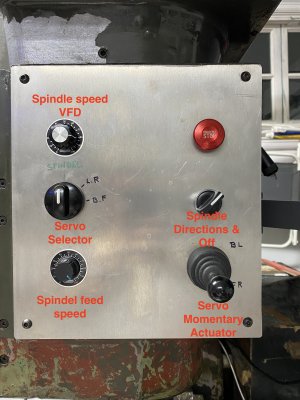
IMG_4539.JPG

I then have a DC power supply turned to max (30V)

IMG_4536.JPG

That goes to a DC motor controller:
IMG_4538.JPG

I think there may be some value in considering the bigger picture at this point
My current thinking is :
- Upgrade manual capabilities - use this to learn with and improve my basic skills
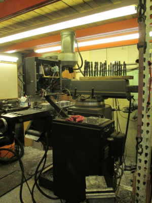
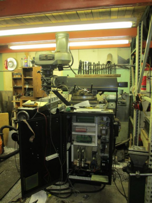
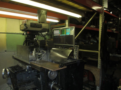
- Cut he box that sticks out over the machine - off - completely.
- Remove the large box on the side - and re-mount to the wall. This will be much nicer to access, and allow the machine to push back 1.5'

At bare minimum - take the screen control box off and let some light in/ lower risk of cracking head open.
Let me know your thoughts regrind the current systems's flaws/ options for creating more grunt at low feed speeds for the spindle.

Thanks!
-CM
 
You are motivating me to get back to work on my 10EE!
 
You are motivating me to get back to work on my 10EE!
Not to get too far off track - but let me say this about the 10EE.
Having never really turned anything in my entire life - I was able to make a super high tolerance part right out of the gate.
The 10EE has totally spoiled me with is ball bearing apron movement and honkin high torque DC motor.
You should do it!IMG_4455.jpgIMG_4462.jpg
 
You should do it!
It'll happen. I'm doing a pretty comprehensive rebuild on mine, and thinking I will go ahead and get the bed ground, then rulon and scrape the carraige in. My DC motor is a bit of a wiring mess, lots of cracked insulation, and a very worn gear in the reduction gearbox. So there is a lot of work to do. I'm just starting to build a new workshop to house the metalworking equipment, so that is going to eat up my time for a while.

I did get my big Monarch (612) running and do have a 1944 CK that is also running, so I'm do have lathe capability. But I expect that the 10EE, when finished, will be the most precise of them.
 
EXT. Thanks. Makes sense. Did not have time to get to the machine today - but will provide this info.
The point may be moot though - if my tools won't drop out, I am probably going to have to have the spindle ground if I want automated operation. Let's see what results we get from your test. Should have at the weekend.

Thanks Jim.
What have you done with all your time?! .
I have it set up like so.

I then have a DC power supply turned to max (30V)
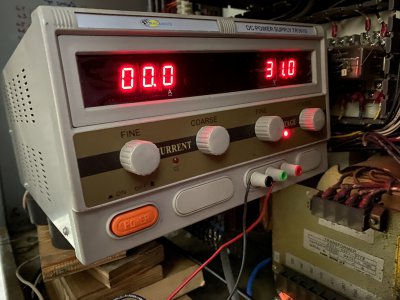
That goes to a DC motor controller:
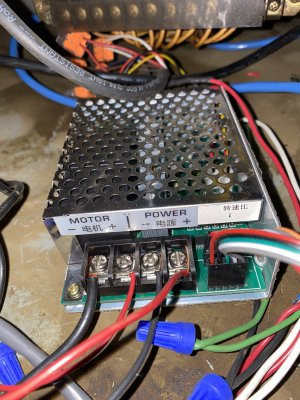

I think there may be some value in considering the bigger picture at this point
My current thinking is :
- Upgrade manual capabilities - use this to learn with and improve my basic skills
- Cut he box that sticks out over the machine - off - completely.
- Remove the large box on the side - and re-mount to the wall. This will be much nicer to access, and allow the machine to push back 1.5'

At bare minimum - take the screen control box off and let some light in/ lower risk of cracking head open.
Let me know your thoughts regrind the current systems's flaws/ options for creating more grunt at low feed speeds for the spindle.

Thanks!
-CM

I have been a little bit busy. https://www.hobby-machinist.com/threads/cnc-lathe-servo-spindle-upgrade.93298/

The poor low speed performance of your axis drives is most likely directly related to the cheap motor controller. They just don't have the sophisticated electronics needed to run smoothly at low speeds. Maybe increasing the voltage would be helpful to get better low speed performance, but it really depends on how the controller works.

One thing you could do is to use the original servo drives and power supply. They have great low speed performance and are well matched to the motors. It is possible to control them with a pot, they don't require computer control.

Removing that big ugly computer box is one of the first things that I would do.

I kept the arm and removed the box
1632416175787.png

1632416230074.png

Then mounted my monitor and keyboard on top of the arm, well out of the way.
1632416362811.png

Mounting the control box on the wall is OK, but one thing to concider is moving the machine in the future. Would make it more difficult.

Adding hand wheels is a great idea. I use mine all the time.

If you need more torque on the spindle, you can always switch into back gear and get about an 8:1 reduction. Plenty of torque to break things. :cautious: You also want to make sure that the VFD is in sensorless vector mode. Turning the mechanical speed down and increasing the motor speed will also give you more torque. I removed my mechanical variable speed hardware and went to a direct timing belt drive with a 1.3:1 step up (motor pulley larger than the spindle pulley). Seems to work fine and will just rigid tap 1/2-13 in steel, with out going into back gear, before I run out of torque.
It looks like a spindle regrind would be a reasonable idea, after a bit more checking to make sure it is really needed. As far as the tool holders sticking in the bore, that just means that the taper is a good fit and is normal. If the tools just dropped out I would be worried, many times they take a light tap to come loose. The vibration of the power draw bar is normally enough to cause them to drop out. I did have my spindle reground when I had it rebuilt. I think the total cost for the 5 bearing upgrade and regrind was about $900.
 
Gracious Jim - lots of good stuff there.
Glad you were able to find something to do with your time...

- Good point on machine moving - which I have already done a couple times.
- I'll share a picture at some point of my arm - it is about 3 x the width of yours - looks like they wanted to land a helicopter on it - and the plate sticks out over the entire table.
- Having considered - I am going to chop off the arm as well - leave the box on there - and that should give me significant improvement.
- EXT also suggested to me that the tool might release with the use of the power draw bar. I will finish my rebuild of that and put it on and see how it goes. Little skeptical - as I am having to give the draw bar a pretty hard whack with a rubber mallet to get it to drop - after some loosening. However - it is possible that the draw bar will "press" it out as it unscrews. TBD.

It looks like a spindle regrind would be a reasonable idea, after a bit more checking to make sure it is really needed. As far as the tool holders sticking in the bore, that just means that the taper is a good fit and is normal. If the tools just dropped out I would be worried, many times they take a light tap to come loose. The vibration of the power draw bar is normally enough to cause them to drop out. I did have my spindle reground when I had it rebuilt. I think the total cost for the 5 bearing upgrade and regrind was about $900.
Have received one quote for regrind only: $1350... Bit more expensive than I was expecting. Will see if I can find a few more quotes. Was yours done on site or did you bring them the head?
You also want to make sure that the VFD is in sensorless vector mode
I'll look at the manual and see if I can figure out where that is.

One thing you could do is to use the original servo drives and power supply. They have great low speed performance and are well matched to the motors. It is possible to control them with a pot, they don't require computer control.
Had thought of this - and it interest me. Lot's of unknowns for me - for example - they might require 3 phase input?
Afterwards - perhaps we can do the dance to sort out what control pot's I might utilize.

*note - I have a second DC motor controller - that has its own power supply. Higher voltage though. Perhaps I could hook that up just to the spindle feed servo to see if it performs better.IMG_2399-3.JPGIMG_1770 2-2-2.JPG
 
A whack with a steel hammer would work better, that's what I used to use. https://www.amazon.com/HHIP-3129-00...N40TUWM/ref=dp_fod_1?pd_rd_i=B00N40TUWM&psc=1

$1350 for just a regrind seems a bit pricy. There are a bunch of spindle rebuilders in the SoCal area. You would pull out the quill and take that over to the rebuilder, that is the normal way of doing it. Maybe that $1350 quote includes removing and reinstalling the quill, and in that case might not be that bad. But the quill is not difficult to R&R, I've done it many times.

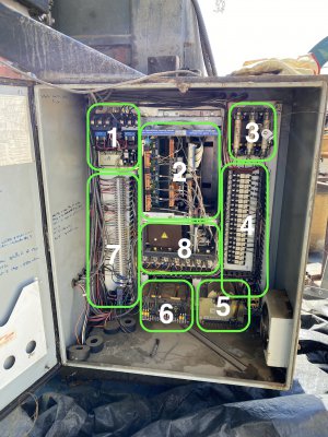
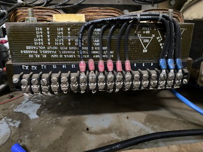
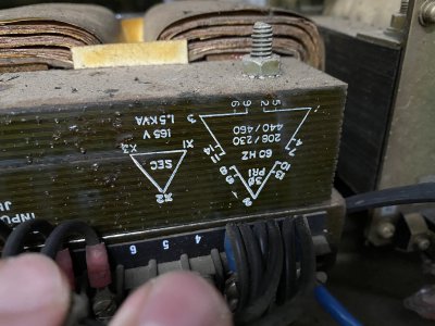
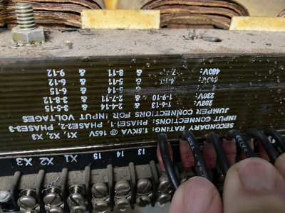
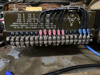
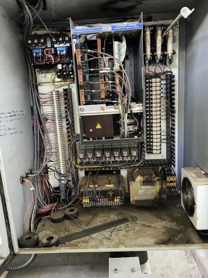
The original servo drives (2) are DC. I don't exactly recall how yours are wired up. But the power feeding them comes from a DC power supply (8) fed by the transformer (6). Most likely 100 - 120 VDC output. As far as I know, the only 3 phase requirement on your machine is the spindle motor. Worst case would be to modify the DC power supply for use on single phase, very simple. Pulling that brown cover off of the power supply would tell the story very quickly.
 
behind door #8 (brown box).
IMG_4549 2.JPG

I'm interested to understand how I would instruct the servo drives (2) could be instructed to move the servos.
 
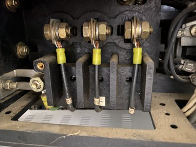
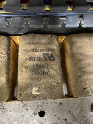
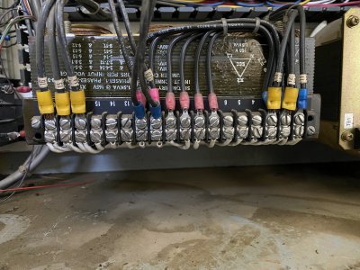
OK, that is a 3 phase bridge rectifier. Easy and cheap to replace with a single phase bridge rectifier. We only need to figure out what the input voltage should be, most likely we can get this information from the transformer (6), just need to look at where wires 14, 15, and 16 are connected and read the voltage from the transformer data plate. https://www.amazon.com/Bridgold-KBP...32432036&sprefix=50+amp+bridge,aps,213&sr=8-3

The servo drives take a +/- 10VDC command signal. They most likely have an onboard source of voltage to power that input. A 10K pot across those terminals with the center connected to the input, just like a VFD, would work fine. These drives may be supplied with a +/- 15VDC power supply from the upper box. If needed, a standard PC ATX power supply can be substituted and we can pull off +/- 12VDC from that.

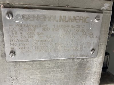
I'm going to need the info from the data tag on the drive housing. It is the tag at the top of the unit. Need to find some documentation on it so I don't have to guess. Failing that, we can trace some cables back to the source to figure out the pins.
 
3 items on the go.
- Plan for bringing the old transformer and servo drives online.
- Measure of spindle runout
- Rehabing and coming up with a plan for the power draw bar.


Ok - that mostly made sense - that is - I understand most of it.
I like the direction for a hand full of reasons.
This would provide robust and smooth movement.
With the DRO, and the addition of handles - I would have a lot more repeatable precision to work with.
Top box and perhaps arm could go (my arm is 2x the size or yours, and sticks clear out over the table).
This would justify remaking my home-made control panel with some upgraded switches (by adding a little depth to it).

BTW - you and Extropic were correct.
While I was not able to get the solenoids to open and close - I was able to direct feed the power draw bar.
When it watched - the tool came loose.
I will post on that separately.

A few more calls found an old German machinist who does mobile spindle service.
$750. Nearly half the price of the other guy.
Been doing this specific process for 15 years.
In the machine repair business since the beginning of time.
More on spindle in following post.

IMG_4556.JPGIMG_4557.JPGIMG_4558 2.JPGIMG_4559 2.JPGIMG_2737.JPGIMG_2467-3.jpg
 

Attachments

  • IMG_4556 2.JPG
    IMG_4556 2.JPG
    2.7 MB · Views: 7
Back
Top