Beauty in The Beast: Webb 5BVK Barn Find/Conversion

best way I've found of drilling a hole on location with a hand drill (no drill press?) is a deep prick punch, then a short thin drill (eg. 1/16") and then your on size drill. The big drill will follow the small hole quite nicely. If you need a slot, drill 2 holes so they just or not quite overlap then use a carbide burr or a file to make the straight sides.

For your stand, I'd suggest a bit of bracing in those side wings. I never cease to be amazed by how much metal can move, plus I'm a belt and braces (suspenders for you lot) kind of guy :)
 
A Brit in Texas typing on a machinist forum?
Gracious - if I made a Venn diagram - your circle would have only one person in it.
I considered boxing in the back side of the seams.
I'd really like to avoid making a "pocket" for chips and oil by gusseting the top.

One thing I have working for me, the machine will not sit on the wheels unless I am moving it.
So only the main beam will cary the load when its in use, and the welds will not be in play.
I am using some high tech FEA on the design ( Feel & Eye Approximation) to determine strength.

However - I will set it up so that catastrophic failure would look like no more than an inch of drop - with outrigger that would not allow the machine to fall over.
I'll post some more pics as I go to make it more clear.
Discussion has been helpful for me to refine my plan.
Thanks for weighing inI
 
You can eliminate a lot of the hole placement concern by using the two pieces independently (Without the central brace). That way you only need to worry about the distance between the holes, side to side.

If it were me, I would reduce or eliminate the need for slotting as much as you can, as I feel that it weakens the structure. Maybe not appreciably but all that weight will be isolated on four points as there appears to be pads on the mill base (not the adjustments), that will be applying all the weight. Another reason why the central brace will not really do anything.
 
PC,
Thanks!
Had to think about it.
If I let the machine act as the beam - it will certainly provide all the stiffness I need.
However - The issue(s) that might not be clear from what I shared is:

The casters are swivel.
If I tried to stand on a single one of the cross members - I wouldn't be able to balance on it and the feeling would be of a knife edge.
It would want to rotate one way or the other out form under me.
Making this worse, the casters are offset and when they swivel, it will change which way the beam wants to rotate in a snap.
This rotational force will be carried entirely by the bolt if I don't add a beam between the cross members to stabilize them.

That said - I will have no choice on first assembly.
Getting fore aft and side to side nailed on a machine with a cast base - and probably hand drilled holes - will be nearly impossible.
Agreed.
Instead - I will try and assemble the cross members on - then cut and weld on the beams in perfect size - if possible...

Worked late last night - to get it ready for today.
Project is kicking my rear and I don't even have the machine yet.
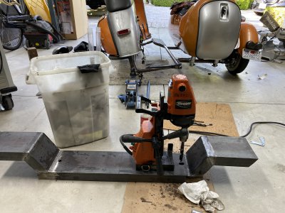
For my sanity - rented a mag drill.
Wholly
cow - is that what milling is like compared to drilling?!
So nice!

Below:
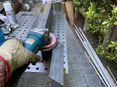
- Won't miss working on the floor... (managed to match drill to my scooter tho!)
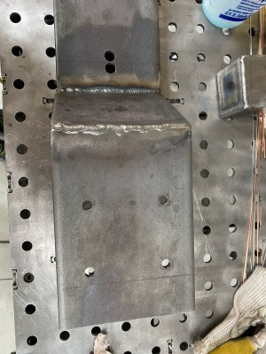
- Lots of holes drilled. Made it a breeze (relatively)
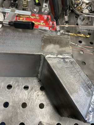
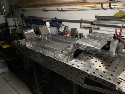
- Gratuitous shot of more welding - because the prior picture makes it look Iike I might have been drunk...
IMG_1979.JPGIMG_1994.JPGIMG_1988.JPG
 
@Charlieman22

Well, the additional support will not hurt you in any measure. Was just trying to save you some steps and material.

You probably already have this covered, but be sure to have large heavy duty washers to put on both ends of your bolts to attached the carriage to the mill.

I am excited for you. While the mill will take some work to bring up to speed, it will make for a great addition to your shop.
 
A Brit in Texas typing on a machinist forum?
Gracious - if I made a Venn diagram - your circle would have only one person in it.
I considered boxing in the back side of the seams.
I'd really like to avoid making a "pocket" for chips and oil by gusseting the top.

One thing I have working for me, the machine will not sit on the wheels unless I am moving it.
So only the main beam will cary the load when its in use, and the welds will not be in play.
I am using some high tech FEA on the design ( Feel & Eye Approximation) to determine strength.

However - I will set it up so that catastrophic failure would look like no more than an inch of drop - with outrigger that would not allow the machine to fall over.
I'll post some more pics as I go to make it more clear.
Discussion has been helpful for me to refine my plan.
Thanks for weighing inI

I'm as rare as a snowflake in south Texas, oh wait... :)

As for reinforcements, I just meant an inside gusset or two to resist the spreading or compression of those joints. Might well not be necessary, but they'll be much easier to add now than later!
 
Well, the additional support will not hurt you in any measure. Was just trying to save you some steps and material.

You probably already have this covered, but be sure to have large heavy duty washers to put on both ends of your bolts to attached the carriage to the mill.

I am excited for you. While the mill will take some work to bring up to speed, it will make for a great addition to your shop.
Papa Charlie - thanks for that - and the good ideas. I think I am going to try and go with a single beam - and headed off now to hunt for hardware that's appropriate. Much appreciated.
As for reinforcements, I just meant an inside gusset or two to resist the spreading or compression of those joints. Might well not be necessary, but they'll be much easier to add now than later!
Good thought. Racing against time - pick up is tomorrow. Still not ready! Should have filled all these shenanigans. Fun.
 
Well, the stand(s) are ready.
I appreciate the good input and challenges.
Was helpful.

I have a truck with a trailer parked out front, and tomorrow is D Day.
Knuckles are cut.
Back is sore.
Beer is cold.

To end my night, I had a tiny metal splinter find its way in to my foot.
I'm sure I'm not the first...
The damn thing was almost invisible to the eye - but not to the mind. Ouch.
Unable to see it like a normal splinter - I pulled out my $30 electronic microscope.
Do you guys have one of these?
I use it for everything - they are - incredible.
When I start milling - I will use it to show some detail - and you guys can tell me what I am doing wrong.
Smooth surfaces look like the moon surface.

Below a few pictures on the eve of pick up for your viewing pleasure.


Current face milling technique:IMG_2004.JPG


Face mill tools. I have a bunch already.IMG_2005.JPG

And of course - the rolling stand(s). Just about complete.
Plan is to cut some angles on the leveling feet extensions/ prime/ install.
IMG_2017.JPG
 
Workbench is fantastic, by the way.

You don't have a mill yet, but everone who does has to deal with chips/swarf collecting everywhere. The U-shaped leveling tabs will turn in to chip buckets and be a pain to clean out when oily, sticky chips seem to weld themselves in every crevice.

If you own a 3D printer (or know someone who does), a friction-fit cover/shroud for the tabs would be pretty slick. Maybe even taper the top a bit.

I don't have a 3D printer myself, but that sort of thing - dumb little non-structural bits - makes me seriously thing about getting one. Fabricating a cover from sheet metal or even plastic sheet would take a while. Drawing up something and sending it to the printer would be significantly less work.
Excellent idea.
It could have a central stem that had a female end that fit over the foot stem.
I tried to minimize any "catch" areas.
I am considering how I might control oil and swarf I my garage as well.
No easy task I'm sure.

Off to load truck. Pictures at 11:00.
 
Back
Top