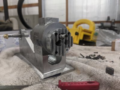
Bob Shores Eagle Hit/Miss Engine Build Thread

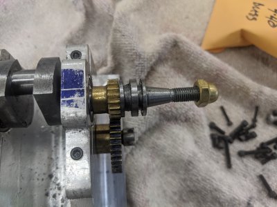
These are actually closer to Module 0.8, they are 32 pitch 14.5 PA gears. the machinist handbook ended up having a chart that claimed that the tooth-cut-depth is not diameter/tooth count specific, and just listed it at about .067.
 
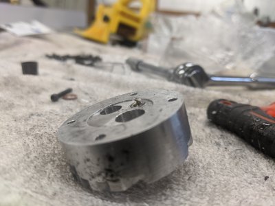
I started the head today (and got through the head aluminum itself!) but I think I messed 2 things up sufficiently that I'll have to re-do it. Anyone building, this is a BIG lessons learned, so pay attention so you don't do your head twice!
Though this is likely usable, I have a couple of things that I would like to do better next time, so I'm going to do it again. I'll share the build log anyway, as it'll give me a chance to point out the mistakes!


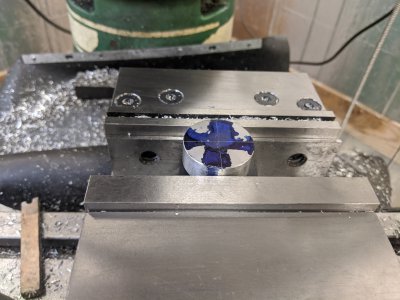
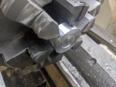
FIRST, I turned a piece of 2" aluminum down to the correct OD. Then, cut it off on the bandsaw, flipped it around, faced it to length, then made the little 'indent'. The indent doesn't have a specified depth, so I guessed here. I think I ended up with about 30 thou. The piston is only going to get within 145 thou of the top of the cylinder, so presumably this is sufficient to not interfere.
IMG_20200507_135924.jpg


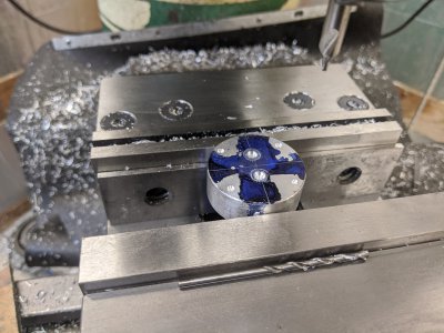
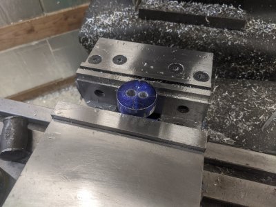
I marked 2 axes as reference, then cut the valve liners from the 'top'. The plans have everything dimensioned from the OTHER side, but that seemed wrong. In retrospect, I don't think it mattered other than getting the straight lines struck.
IMG_20200507_144118.jpg

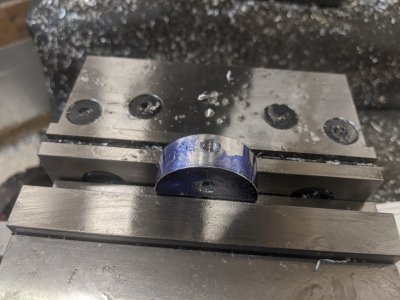
Here is my first 'dummy' move. First, I didn't cut the mounting holes in the previous step, so I cost myself a setup. Second, I setup to drill/tap for the carburetor and exhaust. (I used 5/16-18 instead of 5/16-20 for the exhaust, it seemed like a meaningless change). The problem is that these holes need to go through the liners as well, so I'll have to drill those when I press in the liners! However, I'm not terribly confident in being able to setup these right again.
IMG_20200507_145611.jpg


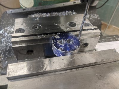
Here I am drilling the mounting holes, just a wasted setup, otherwise not a problem.
IMG_20200507_152153.jpg


Next, I had to drill the spark plug hole. The dimensions tell you where it goes from the other side, and since it is at a 10 degree angle, it took a little trig to get right. It wasn't a big deal. You tap it 1/4-32 for the spark plug.
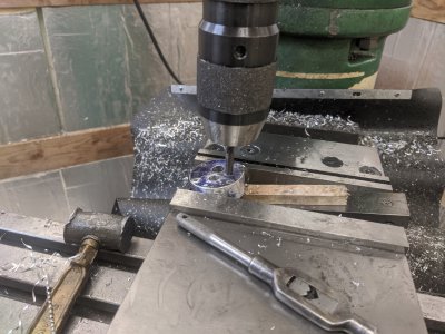
IMG_20200507_153806.jpg


However, here is where I got in trouble. First, I drilled the counter-bore too deep. I ended up having to get a pair of larger copper washers in order to prevent this from interfering later. Second, the counterbore specified is too small for the 'nut' part of my spark plug. ON TOP OF THAT, it is in fact way too small to use a socket on it! I ended up later counterboring in a separate setup to 1/2" so I could get a socket in there, but it ended up just interfering with the exhaust liner. I think it would have been OK, but the result would have been the wrench not working anyway. I have to figure out a way to counterbore less than 1/2", but do so enough that a socket can tighten the nut. I might counterbore with a drill bit little for THAT (something closer to .450 that the outside of my 8mm socket is, AND maybe grind down the outside of one to be quite a bit smaller!).
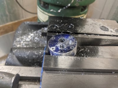
IMG_20200507_155211.jpg

I used a 1/8" endmill here, as I didn't have something closer to the 100 thou. I still stepped over 100 thou, and like how this part turned out.
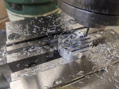
IMG_20200507_160454.jpg

Here it is installed. I counter bored for the bolts as well (good idea!) and a big spot in the lower right (also a good idea) since a washer is going to go there and be held down by a nut. I'll likely do that again.

You can see the lower left of the spark plug getting into the spot for the valve liner.
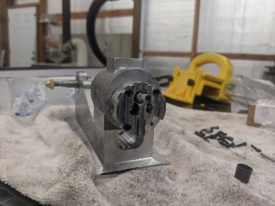
IMG_20200507_170021.jpg

I'm going to try next time making the valve liners FIRST, so that I can press them in and drill them together. I'm also going to be a little more careful about the spark plug socket and see if I have a cheap one I can easily grind down to be closer to a more managable diameter. I'll also be more careful about the depth, perhaps once I can test it with the socket relief, I'll have a better idea of the depth.
 
Hope you don't mind a few questions , are you using just the layout lines to set the head in the vise ? If so would I use a scribe in a collet or indicator base ? I can't see but are you holding it just in the jaws ? I am looking at a PM #1 steam engine kit , my wife wouldn't say anything on the kit but the cost of the small taps and dies would be an issue , couldn't believe I would be spending as much for few of them as the whole kit !
 
Hope you don't mind a few questions , are you using just the layout lines to set the head in the vise ? If so would I use a scribe in a collet or indicator base ? I can't see but are you holding it just in the jaws ? I am looking at a PM #1 steam engine kit , my wife wouldn't say anything on the kit but the cost of the small taps and dies would be an issue , couldn't believe I would be spending as much for few of them as the whole kit !

Yep, I'm setting the layout lines for setting the head in the vice. I then used a square against my vice to set it square. Other than the holes coming in from the side, the orientation actually isn't particularly important, so I wasn't too stressed out about it. You could use a wiggler if you really wanted to check it more closely than that.

The PM#1 is pretty cool looking! It seems like a fun project :) You're right about the taps/dies, I have a few hundred in taps/dies/reamers since I started! I DID find you can get some good deals on NOS taps/dies/reamers on ebay though, so it might be worth checking that out.

Alternatively, I saw a guy on youtube making a #6 that converted everything to metric. If you already have a bunch of small metric taps/dies, there absolutely no reason you couldn' t use those instead. The 'intake' part is the only one that would potentially link to anything outside of the motor, so there is no reason to stress about changing bolt sizes.
 
Day 17: Redoing the head:

This one was pretty easy since I'd done it already :) First thing I did *though I didn't get a picture) was to grind down a 8mm socket's diameter so I knew how much I had to counter bore. I also realized I could do it as a less-deep counter bore than the other one. I still need to grind on it a bit more as it got stuck when I got all the way tight on the spark plug since it is tapered, but I got it enough with partial engagement to know its about right.

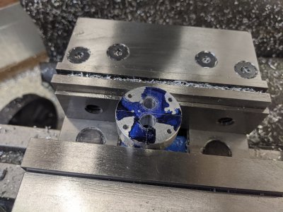
This time, I opted to do this in as few setups as I could, which ended up being the right answer. First I turned the OD, then to length (plus the little 'dimple' for the valve side). Then, I blued it and marked 2 90 degree lines to help with setup. Then, I found the center with an edge finder, then used the DRO to center-drill all the holes. 4 mounting, 2 valves, and the spark plug:
IMG_20200508_144000.jpg

IMG_20200508_144803.jpg

Then I continued with the DRO to drill all of the holes. #32 for the mounting holes, 5/16 and 3/8 for the valves.
IMG_20200508_145614.jpg

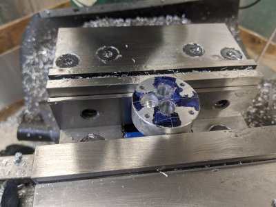
I used the sine bar to setup for the cut, found the dimple I made above with a a center drill, actually center drilled, then drilled for 1/4-32. Then tapped 1/4-32. THEN, I did the math based on my depth and the size of the threads on the spark plug and counter-bored 3/8 for the copper washer/bottom. THEN 13/32 for the socket made above, but only to the depth required. I managed to stay far enough away that I'm pretty sure I have a decent wall between it and the valves! Its a double-counterbore, but it makes it less dangerous since it is at a 10 degree angle.

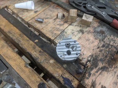
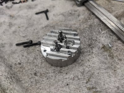
I missed a picture of the spark plug drill setup, but this is immediately after. I then cut the fins in just like before.
IMG_20200508_153145.jpg

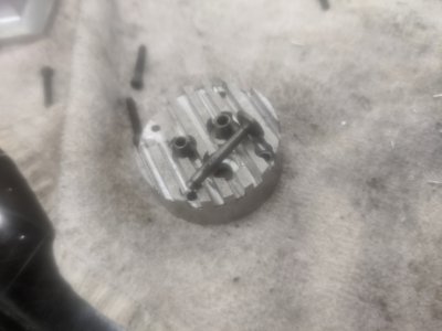
Here is the spark plug stickout. It seems JUST about perfect! This was my biggest concern with the bad version of the head, but between the gasket and fact that the piston doesn't go to the top, this should be perfect.
IMG_20200508_160413.jpg

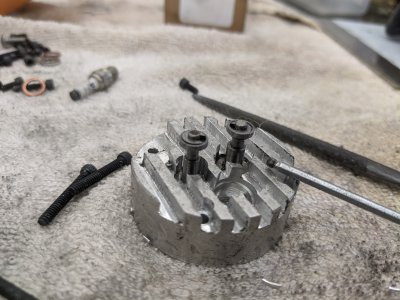
And Installed!
IMG_20200508_160710.jpg

It'll have to come back off to press in the valve guides, and to setup all the valve stuff, but I've got it bolted in to keep things together for now :)

I spent a bit of time working on one of the valve guides, but I screwed up my math and made it 70 thou too short. SO, it was just practice :) I'll have to give it another shot tomorrow, when I hope start to to make both guides, both valves, and perhaps getting into the retaining/spring parts. I'm hoping to have all of the 'head' stuff done before starting anything else.

I also got parts to work on both sides of the crankshaft. I have to make the breaker assembly on the 1 side, and the thimble on the other, but then I should be able to actually get the flywheels worked on, which would be exciting!
 
Day 18: Valve guides!

Today I went to town on the valve guides! I only had about 2 hours to work, so getting these done successfully was nice! I also noticed that I messed up the one from yesterday in more ways than I realized! Anyway, this one was successful!

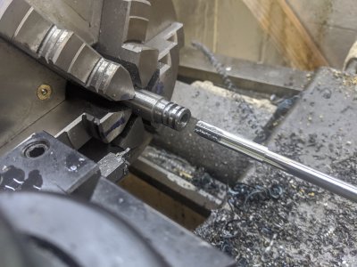
These pictures are from the 2nd one I did. The annoying part is that they are both different sizes. The intake is smaller than the exhaust in each dimension, and I discovered that the smaller bits in my normal numbered drill bit set don't really like O1. I lost about 2 inches of material to 3 different broken drill bits! The plans call for a 109 thou through hole, but I chose to go with 111 instead, since the #32 bit I had was nice (and I'd broken my 109 and 110 thou bits :)). The bigger one was a more 1/8" bit, which I have a better one. It was through with a small hole, then counter bored with a larger one for the bottom of the valve. IMG_20200509_125129.jpg

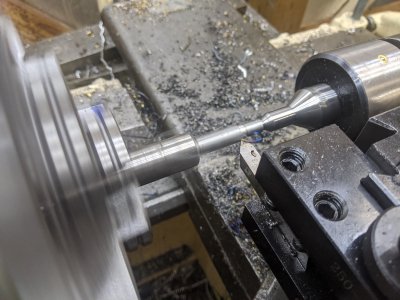
On the smaller one I had to turn the OD down to 5/16" (the other one was 3/8", which matched my stock, so I didn't have to do this part! I also had to 45 degree the inside for the valve contact surface. These will be lapped later. I used my combo square head to set the angle.
IMG_20200509_130017.jpg

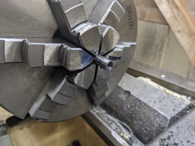
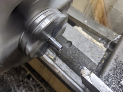
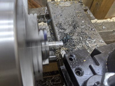
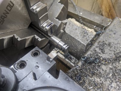
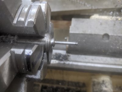
Then I had to turn down the smaller section, which ends up being a spring guide. My large tooling was a bit of a challenge on this because it kept getting in the way! On the first I used a left and right hand tool alternating to clear out the material, but this one I just used a thread tool on power feed to clear up the material, and it did a surprisingly good job. Then I used a (right hand?) tool to go left to right to square up the shoulder.
MVIMG_20200509_130320.jpgIMG_20200509_130502.jpg
IMG_20200509_130502.jpg

And here it is squared up! I polished it a little, then parted off.
IMG_20200509_131203.jpg
I then flipped it in the chuck and removed the end of it to length.
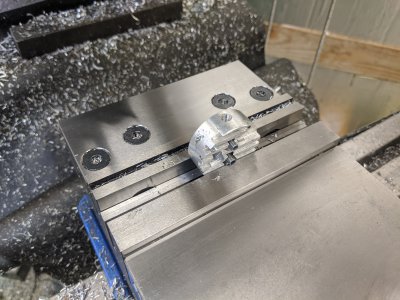
IMG_20200509_131720.jpg

Finally, some bearing-retaining loctite and a wood vice pressed it in all the way! The 3/8" one was reamed and the actual size of the precision ground rod, so it was a press-fit anyway, the smaller one was a drill bit and a turned OD, and it was a tight slip-fit. The loctite will make sure they never move :)
IMG_20200509_132634.jpg

I spend a few minutes trying on a valve, but I didn't really like how it was turning out. it was good practice to figure out the process! They'll be my next project.
 
Ugg... I spent the day trying to make a valve. There is a really thin portion (85 thou) that seems to bend/break if you look at it funny, so I went through about 5-6 tries at a valve with no successes. I'm going to have to order some more O1 tool steel just to make them! I might move on to other parts for a few days to make sure I actually get to make all the parts I need out of the stock I have.
 
Day 19: The Thimble and a finally a valve!

First, I got a reamer in the mail for .376, so I had what I needed to make the thimble. This is the only part I needed to make out of the 3/4" O1 tool steel (vs the 3/8) that I was burning through attempting to make my valves (after killing all the 3/8). SO, I wanted to make it first! The purpose of the thimble is to interact with the two arms of the governer and 'block' the ability of the exhaust port to open, causing the engine to not fire (the 'miss' part of the hit/miss!). This process was pretty easy. I turned the OD down in the 6 jaw.

IMG_20200512_143648.jpg

I ground a HSS bit down to the right width for the smaller part, which is 77 thou. It ended up being a little bit of a scary small cutter, with half the bottom unsupported due to the taper. I used it to cut both slots (the small one and the large one!)
IMG_20200512_150420.jpg

Then I used it to start the 'parting' cut. I then drilled/reamed the center to 376. I didn't have my 1/64th under drill bit here, so I used a 1/32nd under. This was not exactly a mistake, but not a great idea. the reamer had quite a bit of trouble getting into the hole as a result. I ended up having to 'peck ream' as a result.

IMG_20200512_151041.jpg

And installed! Dirty as all heck, and covered in oil/grease (the bottom of the channels are flat, that top left one is just oil), but appears like it'll be functional! I might find that I need to take a little material off the back of the gears to allow it to move back and forth though, it is surprisingly close to where the flywheel will be.
IMG_20200512_151942.jpg


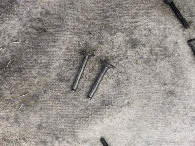
I then went back to trying a valve. I'm getting good at this part :) After ruining my first one, I tried again. here it is entirely profiled. The part-off mark on the left is the bottom of the valve, the indent on on the right that is deeper (the left of the two) is for the retaining horseshoe washer, and the other is to mark the 'end' of the valve. I opted to make the stem 'indent' (which was supposed to be .082) significantly bigger than the plans, since it was bending/breaking on all my previous attempts with the slightest touch.
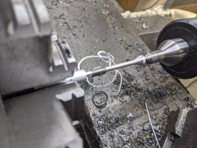
IMG_20200512_162746.jpg

I used a cutoff wheel and an angle grinder to cut the top, then shaped it a bit with files. I then used files and some sandpaper to turn the diameter of the valve down a little more to smoothly/tightly fit the valve guide.
IMG_20200512_163750.jpg

Finally, I parted it off, sanded the bottom with some 500 grit, and called it a night!

IMG_20200512_164359.jpg


I have 1 more of these to make now (the smaller one, yikes!), but hopefully I have enough material. If not, I ordered some additional O1 to cover me for more mistakes ;)
 
Day 20:Finally finished the last valve...
If I never make another valve, it'll be too soon. It took me 2 more tries, and got me down to just about the last of my O1 tool steel. I've got some 5/8" coming too that was there in case I needed it, but it looks like I might not! Oh well, more good metal for the future projects pile :)

This was in the middle of the first try of the valve. This one failed because I had my tool to make the groove for the horseshoe washer slightly low, and it snapped my valve.
MVIMG_20200513_135417.jpg

After finishing, I lapped them both with some green lapping paste on both the shaft and the 45 degree area. They both seem to lock up tight now! With a little oil on them, they both 'pop' when disengaging from the valve seat.
IMG_20200513_151856.jpg

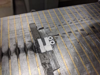
Next, I had to make the horseshoe washers, which go in the grooves and help hold the valve in (along with the spring retainers and spring!). The plans call for tool steel, so I continued using my O1. I turned the OD, then drilled the center for the smaller valve, then parted, then drilled for the large valve, then parted. However, I was about 10 thou too large (intentionally). SO, they went on the surface grinder to thin them down to the proper size:
IMG_20200513_155245.jpg

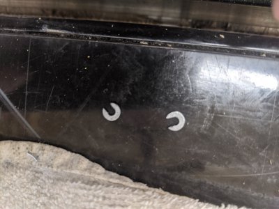
The next part was the worst, making a pair of washers into horseshoe washers. The plans say to use a cutoff wheel, but I imagine they mean a dremel, which I don't have. I DID have some small harbor-frieght burrs (for some reason!) that came with their little rotary tool kit. The rotary tool died years ago, but the tools were sitll in a drawer. I used that to break through (holding them in teh mill vise) then used a small auger-bit file to make them horseshoe shaped. They both fit nicely around the valves.
IMG_20200513_162238.jpg

Here are the washers in place!
IMG_20200513_162301.jpg

Then, I needed to make the spring retainers. The spring pushes up against them, and they are held in by the washers above. I ended up getting to make 3, since I dropped the 2nd one on the way to grind off the parting-tool leftover. I've got them manually pushed up and held with some shmoo, but this is how they will work. The springs should hold them up.
IMG_20200513_173526.jpg

Next, I will likely make the springs themselves, plus 1 or two more parts that I'd consider part of the head. Hopefully those will go more easily than these parts!
 
Day 21: Sproing!

So, First, I remembered that I have to drill /tap the carb and exhaust ports! My first try at the head I didn't wait this long, but this time I wanted to do it with the cylinder liners in place. Intake is 1/4-28 per the plans, exhaust is 5/16-18 (not -20!) as I didn't have a 20 TPI tap :) IMG_20200514_132703.jpg


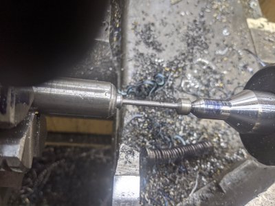
Then, I got to making a spring arbor. I turned it out of a piece of aluminum, right in the middle of the range that i calculated with a mandrel calculator. I left the tip on so that I could use it with tail support. the downside is that made these one use!

The first spring I didn't get my halfnut in (at 18RPM, it wasn't obvious that it wasn't moving :/) so the spring wound pretty (left/right wise). I was able to manually stretch it to the right size. The exhaust spring was first!
IMG_20200514_140816.jpg

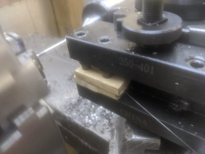
Here's some slightly better pictures of how I tensioned it. I used a couple pieces of wood as tension in my tool holder, and it worked great!
IMG_20200514_143101.jpg

IMG_20200514_143106.jpg


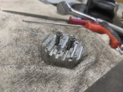
And here they are installed! I still have to lap the valve stems a little I think to run smoothly, but the springs work!

IMG_20200514_145435.jpg
 
Back
Top