- Joined
- Nov 25, 2015
- Messages
- 8,298
I kept calling this a brake in the POTD.. sorry. brain fart.
I wanted a tool less lock. It originally came with a hex cap bolt. I created a new one with a tool less design, but it required an enormous amount of torque to pull the casting tight. A horrible desing. I always noticed in Utube videos that the BP had a super sweet soft flick of a handle to lock the quill. Greg @f350ca gave me some insight to the lock. I originally thought it was a single slug, but he explained that it clamps from both sides. I examined the head, without taking it off, and did not think I could do what needed to be done. It appeared that the existing bolt was too far from the quill. There was 1/16 of an inch from the edge of the bolt to the quill. That may not sound like a lot, but it is.
Having ruined multiple parts from the lock not holding, and doing a job where the quill kept dropping I realized it's time to make my life easier. The lock is the first step.
I'll bring you through a progression of steps. I did not have a way to mill the new hole. I only have one mill, and my lathe is an SB9, the head wouldn't even fit on the cross slide it's too big. So mounting it there and using a boring head on it was not an option either.
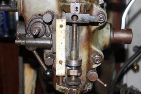
This is the head as it was received before I rebuilt the mill. That large hex head bolt is the quill lock. So pick up a wrench everytime you need to lock it...

That slit in the casting is what the bolt squeezes to tighten the casting around the quill.. The casting is thick, so it takes a lot to tighten it up.

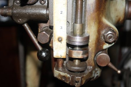
After I rebuilt the mill, one of the first projects was to make it tool less. So I created the new bolt with a swiveling handle.


This didn't work as I hoped. It was tool less, but it was difficult to lock, and sometimes it slipped. There was not enough leverage without a wrench and it really doesn't hold that well.
SO NOW TO MAKE A CHANGE.. TIME TO MAKE IT LIKE THE BRIDGEPORT AND CLONES
Normally a drill press can't do the job that I needed to do, but desperation requires taking risks and knowing the limits. The quill on a drill press is not firm enough, it rocks back and forth. There's no draw bar to hold the tool in, and the side wards cutting will knock it loose. I took out a roughing end mill at first and drilled with it to start offsetting the hole. Now it would be oblong, but it would give me a fighting chance at moving it over, once I had room I could take little bites with a boring head and round it out, and move it over more.


The depth of cut on this is big for the drill press. And the cutting tools. I didn't have a long end mill in 1/2 inch. I had various boring bars but the limit was I only wanted to go to the split, I didn't want to go past that. So if things failed, I could still use the old bolt method. Once I bored a complete hole to the split, I then proceeded to take out the threads and open the back of the casting.


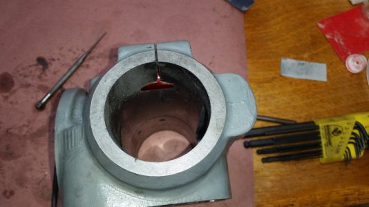
The bottom of the hole has breached the casting, but I can't remove it all. I have to leave it as is. I took a die grinder and cleaned up the burs in the back, where it broke out.


Inside the casting I took the die grinder and deburred the hole in the casting. That white around the hole is the ground area. I slipped and got a little outside that .. I wound up taking some emery cloth and smoothing it out.


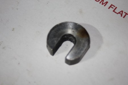
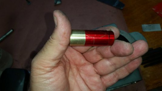
Here we are starting to create the brass slug that becomes the lock. Due to a little narrowing at the very bottom of the hole, I left a step at the bottom so that it would slide in to that last 1/16 - 1/8 inch of narrowed area.


I wanted a tool less lock. It originally came with a hex cap bolt. I created a new one with a tool less design, but it required an enormous amount of torque to pull the casting tight. A horrible desing. I always noticed in Utube videos that the BP had a super sweet soft flick of a handle to lock the quill. Greg @f350ca gave me some insight to the lock. I originally thought it was a single slug, but he explained that it clamps from both sides. I examined the head, without taking it off, and did not think I could do what needed to be done. It appeared that the existing bolt was too far from the quill. There was 1/16 of an inch from the edge of the bolt to the quill. That may not sound like a lot, but it is.
Having ruined multiple parts from the lock not holding, and doing a job where the quill kept dropping I realized it's time to make my life easier. The lock is the first step.
I'll bring you through a progression of steps. I did not have a way to mill the new hole. I only have one mill, and my lathe is an SB9, the head wouldn't even fit on the cross slide it's too big. So mounting it there and using a boring head on it was not an option either.
This is the head as it was received before I rebuilt the mill. That large hex head bolt is the quill lock. So pick up a wrench everytime you need to lock it...
That slit in the casting is what the bolt squeezes to tighten the casting around the quill.. The casting is thick, so it takes a lot to tighten it up.
After I rebuilt the mill, one of the first projects was to make it tool less. So I created the new bolt with a swiveling handle.
This didn't work as I hoped. It was tool less, but it was difficult to lock, and sometimes it slipped. There was not enough leverage without a wrench and it really doesn't hold that well.
SO NOW TO MAKE A CHANGE.. TIME TO MAKE IT LIKE THE BRIDGEPORT AND CLONES
Normally a drill press can't do the job that I needed to do, but desperation requires taking risks and knowing the limits. The quill on a drill press is not firm enough, it rocks back and forth. There's no draw bar to hold the tool in, and the side wards cutting will knock it loose. I took out a roughing end mill at first and drilled with it to start offsetting the hole. Now it would be oblong, but it would give me a fighting chance at moving it over, once I had room I could take little bites with a boring head and round it out, and move it over more.
The depth of cut on this is big for the drill press. And the cutting tools. I didn't have a long end mill in 1/2 inch. I had various boring bars but the limit was I only wanted to go to the split, I didn't want to go past that. So if things failed, I could still use the old bolt method. Once I bored a complete hole to the split, I then proceeded to take out the threads and open the back of the casting.
The bottom of the hole has breached the casting, but I can't remove it all. I have to leave it as is. I took a die grinder and cleaned up the burs in the back, where it broke out.
Inside the casting I took the die grinder and deburred the hole in the casting. That white around the hole is the ground area. I slipped and got a little outside that .. I wound up taking some emery cloth and smoothing it out.
Here we are starting to create the brass slug that becomes the lock. Due to a little narrowing at the very bottom of the hole, I left a step at the bottom so that it would slide in to that last 1/16 - 1/8 inch of narrowed area.


 PM coming .
")