Custom build of a crankshaft trueing stand

Nice, to be honest.. this was a first for me aswell. My race bike big end bearing was about shot and in need of replacing so I thought it cant be that hard? Well... it took me ages to get the crank trued up, it took a while for me to realise where to give it a wack.

I enjoy making tools also but lacking a milling machine makes things more challenging sometimes.

I will follow your progress with great interest, keep up the good work!

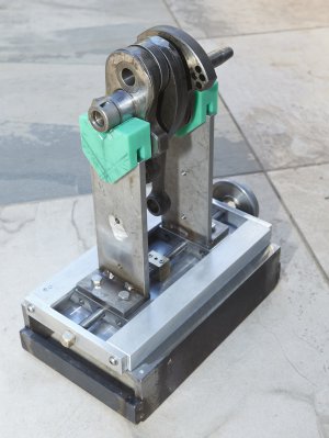
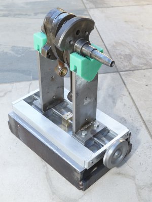
One thing I will mention is that my DTI was picking up on the ball bearings rotating, next time I would make some discs with bushings, but the V's you have will work perfectly well.

Sent from my SM-G950F using Tapatalk

I have not actually pushed my crank apart yet. And that means I haven't pushed it together. Did you build special tools to hold the crank while you pressed out the crank pin. I can see you have a single where as my engine is a twin, so a few more variables. In theory I appreciate the long winded process of pressing the crank back together....... did you check the runout in stages as you pressed your crank together?

In regards to bearings on the stand, I am planning to mount a set of bearings (which are removable) but only for use to do a static balance of my flywheel/clutch assembly. My bike has a dry clutch like a car so the combined mass of flywheel and clutch pressure plates etc is considerable. I thought I could get a smoother engine by making sure that assembly is as balanced as I can make it.

Mal
I have ridden a few modern Beemers (GS1200s and RT1200s) and what strikes me a curious is how they seem to shake at idle but are beautifully smooth at speed. I don't quite understand how the shake at idle doesn't increase at speed.
Sorry for the tangent :D
 
I have ridden a few modern Beemers (GS1200s and RT1200s) and what strikes me a curious is how they seem to shake at idle but are beautifully smooth at speed. I don't quite understand how the shake at idle doesn't increase at speed.
Sorry for the tangent :D

David

We also own a R1200GS and while it has twice the engine capacity of our old bikes it is way smoother in terms of engine vibration. You do raise a good point and I am no engineer so can't give you a reason. The new bikes do have a balance shaft in them which is part of the answer but not really what you are talking about. Even the old bikes without a balance shaft have a rocking motion at idle which smooths out once the revs build a little.

Mal
 
The first time I rode a Beemer I near dropped it when I blipped the throttle! The rocking is real!
 
The first time I rode a Beemer I near dropped it when I blipped the throttle! The rocking is real!

There are two issues here. One issue is the balance between horizontally opposing cylinders, which I think gives us the rocking motion. The second issue is gyroscopic precession which is caused by the crankshaft running in line with the axis of the bike rather than across the bike like most Japanese four cylinder bikes. I think the action that caused you to nearly drop the bike may have been caused by the second issue.

Mal
 
I did do a short video of the feet being moved my the cordless drill but alas the file was too big to upload.
Suffice it to say the device is working as planned.
The second photo shows the thrust bush which is needed to make the whole show work.

Just need a turn wheel and to get the legs finished and it will be test time with the crankshaft.

MalMAL_0783.jpgMAL_0786.jpg
 
Well folks, thanks for watching but that is phase one completed.
There are a few additions I will make.
1. a set of roller bearing as an alternative to the green plastic tips. The bearings will be used to do a static balance on my flywheel and clutch assembly.
2. I maight put a little handle on the handwheel to make fast adjustment easier to achieve.
3. Some sturdy adjustable mounts for the dial gauges. I have magnetic stands but sometimes I find them not 100% to my taste.

I am very happy with how smoothly it can be adjusted and given it probably weighs in at 8kgs, there is plenty of stability.

Mal
 

Attachments

  • MAL_0792.jpg
    MAL_0792.jpg
    311.4 KB · Views: 22
  • MAL_0793.jpg
    MAL_0793.jpg
    352.6 KB · Views: 27
Last edited:
Super work Mal, makes me want to turn the handwheel.
 
Super work Mal, makes me want to turn the handwheel.

I am just a self taught person and this is probably the most indepth single project I have undertaken.
So quite satisfying to see ideas turn into 3 dimensions and for it all to work pretty good.

Thanks for taking the time to comment.


Mal
 
Starting to work on stage two of the stand. This is the frame to hold the dial gauges. Shaft will be able to be mounted at several heights to suit the task at hand.

Also had the new timing gears turn up, so had a slight detour to machine up some custom shafts so I could check the backlash on the gears prior to final assembly. Just in case they were wrong size and had to be exchanged.

Mal

MAL_0831.jpgMAL_0832.jpgMAL_0834.jpgMAL_0836.jpg
 
Last edited:
Back
Top