Enco 110-2032 switch wiring

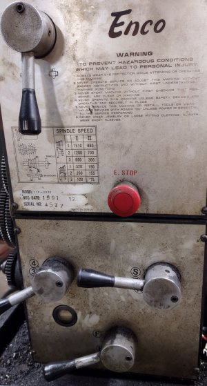
But you have an Enco correct? Is the front panel the same as the G4003? Show me a pic of your front panel
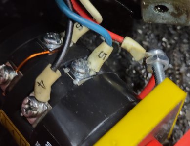
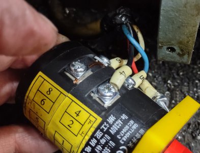
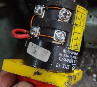
Where did you buy the new switch from? Amazon? What is the full part #? I can see HZ5B-10/2 and there should be some digits after that-
We need to verify the internal contacts of the new switch somehow.

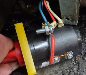
BTW have you checked to see that the new switch will mount up the same as the old one? Mounting holes and shaft size the same?
If not I would hold off on modifying the machine until we verify the switch internals

Would you be willing to re-purpose the inching/jog button? There may be a way we could make the new switch work
with a slight re-wire but we would need to change the inching button into an "enable" button
 
Last edited:
This is not going to be a high use lathe. It is beginning to sound like a great deal of effort on a lot of folks parts. I could live with a simple external switch mounted on the gear head cabinet.

I did look at the modifications required to adapt the new switch to the lathe. Doable with some effort. I'll attack a pic of my lathe panel.
At this point if I can get this lathe to turn down and thread I'd be happy.
 

Attachments

  • IMG_20221028_100245321.jpg
    IMG_20221028_100245321.jpg
    231.1 KB · Views: 12
I think I have a hookup you can try- if it doesn't work nothing bad will happen, it just won't work, or might just run in one direction.
On your new switch:
1) Tie 1 and 3 together with jumper wire, connect lathe wires 3 and 6 to those.
2) Connect lathe wire 4 to switch 2
3) Connect lathe wire 5 to switch 4
Try that and report back

Is there another panel with more buttons? I only see the E-stop..
 
Last edited:
I attached per instructions and it did nothing. (I did splice #3 wire to a short red wire to reach the connector). See attached.
I also tried the temporary forward and reverse switches while all of this was connected and it still works in a temporary fashion.
It's a good thing I don't repair lathes for a living. I'd be broke with many cursing customers.
Thanks Danny
 

Attachments

  • IMG_20221028_125815338_HDR.jpg
    IMG_20221028_125815338_HDR.jpg
    292.9 KB · Views: 5
  • IMG_20221028_125805145_HDR.jpg
    IMG_20221028_125805145_HDR.jpg
    286.9 KB · Views: 5
  • IMG_20221028_125820750_HDR.jpg
    IMG_20221028_125820750_HDR.jpg
    308.9 KB · Views: 5
  • IMG_20221028_125756594_HDR.jpg
    IMG_20221028_125756594_HDR.jpg
    302 KB · Views: 5
Are you sure you are IDing the terminals correctly? This is where a continuity checker would come in handy
How about this: disconnect the switch and connect 3,4 and 6 together. Should run forward. If so, then try 3, 5 and 6 together; should get reverse.
Let me know
 
Connected the 3,4 and 6 wires you indicated and nothing happened. So I tested each wire unconnected. the #6 is the only wire showing voltage (24V). The rest showed nothing. I also tested the connection where the wires hook to the cable going to the switch. Same reading #6 had 24 volts, the others nothing. Obviously there is something wrong in the electrical control panel and the old switch was ok. Also #5 wire has no voltage.I Ied you in the wrong direction due to my ignorance and advice I took from an electrician.
 
Questions/checklist:
1) Didn't you mention your meter was broken? Or only partially? Still reads AC volts?
2) The diagram might not match the machine or there is a failure- I think we should re-measure again- I'll mark up the diagram and repost
3) You still need to post the whole part # for the switch (unless there aren't any more digits than HZ5B-10)
4) I still want to see the rest of the buttons- start button, etc.- being as how your machine is different than the Grizzly
5) Does the inching/jog button work?
 
Last edited:
Measure between points A and B/3 on the diagram you should see 24 volts AC, if the lathe is powered on.
Then, connecting the two switch wires 3 and 6 you should hear the little relay M3 click, latch, and there should be 24v between A and C/6.
Separating the wires 3 and 6 and hitting the E-stop button should make the M3 relay drop out.
If no click or voltages then we need to investigate further
-M
Encoelecm2.jpeg
 
Last edited:
Forgot to mention- you may need to temporarily extend the switch wires 3 and 6 to do the tests if the contactor box is behind the lathe- any kind of
thin, insulated wire would do.
You need to be able to get your nose right in there- you might even be able to visually see the little relay pull
Be careful- you might want to put some tape on some of the exposed terminals for safety's sake when you are testing
Keep the rotary switch disconnected for now. I suspect the little relay may be faulty
 
Last edited:
Back
Top