Enco 110-2032 switch wiring

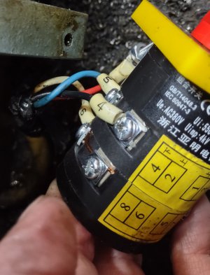
1. Other switch numbers :
GB/T14048-3
IEC 60947-3
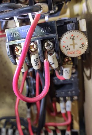
2. The Inch/Jog switches work. F&R.
I was getting ready to do some more testing and discovered something. Look at the upper portion of pic. #2. There are three metallic links going from the (relay box?) To the inching box connector. The two on the left are in tact and connected but the one on the right W/6 Has a section missing.
I felt like you might need to see this before I proceeded with your testing recommendations.
Let me know and I'll pursue testing.
Thanks Danny
 

Attachments

  • IMG_20221028_125820750_HDR.jpg
    IMG_20221028_125820750_HDR.jpg
    204 KB · Views: 8
  • IMG_20221029_175322370_HDR.jpg
    IMG_20221029_175322370_HDR.jpg
    219.6 KB · Views: 8
Here is a pic you requested I forgot about.
 

Attachments

  • IMG_20221028_100245321.jpg
    IMG_20221028_100245321.jpg
    243.7 KB · Views: 9
Are you saying there are no other buttons on the machine? Just the red E-stop?
No start button? No power on light? If so then the diagram doesn't match your machine
Do the tests anyhow. See what happens
I see the metal links but don't know what it means
I see something else fishy: the little Omron relay is a 2 pole not a 3 pole like the diagram- that's a puzzle
We're pretty much shooting in the dark here without a proper diagram.
See if any combinations of those 4 wires will do anything at all- maybe we'll get lucky
 
Last edited:
As to the wiring diagram in the manual I bought as an aftermarket item, I agree, it's for another model.
In my research I have found very little on this model. It must of had a short life. There is no start/stop button. The long rod with a lever that connects to the switch is the only way I see to power the lathe. No light to indicate on/off. Perhaps this lathe was designed by Satan.
It's been so long since I've worked with this lathe my old brain just can remember. I never had any problems with what I used it for. I'll do some more checking and testing. I will be gone most of this coming week. I'm not abandoning the lathe just will be out of touch for a bit.
Perhaps someone on this sight will have a diagram.
Thanks Danny
 
Sorry, I tried. There should be some combination of those 4 wires that will activate it if there is nothing wrong otherwise.
If it was mine I would probably re-wire it in a simpler way but that may be
more than you're willing to tackle
Let's let it rest for a week and maybe we can explore other options
-Mark
Yep, Satan
 
I agree and appreciate all you've done.
One more thought. Could you post a request for a copy of the original wiring diagram on the appropriate forum in Hobby Machinist?
I can also do this (I think) but I'm not very familiar with the site as a new member and don't know if I'd choose the best way to do this.
If we had this diagram I believe we could find the problem and be able to make the correct move.
Again, I appreciate your help and patience.
Thanks Danny
 
Danny: I just did some more research and apparently there is no published diagram for that exact model. It seems the factory made some last-minute
changes which never got documented. I've got a line on some more info which I'm going to pursue.
I also found that Harbor Freight sold that same lathe years ago- made by Tida in Taiwan. No manual available from HF either.
But never fear, Smith is here. We can dive back into it again next week.
-M
 
Great.
I'm not surprised I bought an oddball. Seems to run in my blood. I know this is not unknown. A lot of the firearms I run across have many "undocumented" generational changes.
Thanks Much,
Danny
 
One last thing: You said the F/R lever on the front panel works? Runs the motor forward and reverse? Meaning the apron lever forward/reverse is the only feature that doesn't work correct?
If this is true isn't the lathe functional now? Except for the apron lever It's still basically running correct?
-M
 
No the lever attached to the apron and rotary switch(the one I bought a replacement for) did nothing and just for fun I shifted ever lever on the control panel and nothing happened. What does cause it to run forward and reverse is the two buttons found inside the electrical control panel. See attached photo of buttons. They are marked
C-16G.
 

Attachments

  • IMG_20221029_175557865_HDR.jpg
    IMG_20221029_175557865_HDR.jpg
    376.3 KB · Views: 5
Back
Top