Erich's Benchtop Gear Hobber Project

A little more work today! One thing I DO need to do is find some sort of metal project box to go UNDER the machine that is of a good size (IIRC, 13-1/4" x 9", 2" high) to hold the power supply. If anyone has a good source of something like this, I'd be grateful if you can share!

Today was a bit of a "do what I can while I can", since the mill has a setup that is a pain to take down that I am waiting on something to finish up, so I don't really want to tear into it just yet, so I tried to stick to lathe work.

I started out by reaming and broaching the plastic gears:
PXL_20230317_205939016.jpg


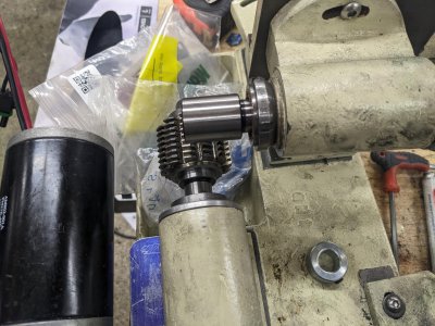
The second thing I did, was decided I need the 'hob' holder adapter, its the MT2 adapter that goes in the hob spindle. First, I took a hunk of aluminum, drilled and reamed it for MT2. I used the drawbar to hold one of the MT2 blanks, centered it in my 4 jaw, then turned it down so the hob will fit:

PXL_20230317_213551557.jpgPXL_20230317_215613846.jpgPXL_20230317_215619573.jpg


The hob is quite a bit longer than the MT2 blank, so I made a washer + hob support in 1. This should keep the pressure from the bolt even:

PXL_20230317_231033781.jpg

I still need to cut a key in it, but thats project for another day :)
 
As you've all noticed, I've been lazy lately and haven't been playing in the shop lately (at least on this project)! BUT, I got a good day of it today. I opted to start on the motor-mounting bracket. The plans have no place to put the motor (nor any design for it) so I'm on my own. I chose a FIRST robotics motor called a 'CIM' motor, with the "CIM-Sport" 4:1 gearbox. Mixed with the 4:1 ratio for my belt, I have a 16:1 ratio, which should give me about a 350 RPM max speed, and ~40 RPM 'minimum' usable, which seems about right for now. The nice part is if I decide to change it up, I can do so with the belt instead of the gearbox.

Despite the plans not having any place for the motor, the original seems to have the motor off the side of the hob spindle, and the hob spindle has a pair of interesting bosses on it. So I decided to use that to bolt the 1/2" thick aluminum plate to the spindle housing.

First, the motor side, I just flattened the boss:
PXL_20230405_211635119.jpg
PXL_20230405_212142647.jpg

Next, I flipped it and flattened the round bosses:
PXL_20230405_212303455.jpg

I drilled clearance hole and counter-bore for a 1/4"-20 SHCS:

PXL_20230405_213923702.jpg

Next, I chopped a ~4 1/2" long hunk of aluminum 1/2" plate from a big scrap I picked up.

PXL_20230405_214455641.jpg

I apparently missed photographing it, but I then flattened 1 side as a reference surface, then drilled/tapped 2 holes 1/4-20 at the 3" spacing of the bosses above, that way I can bolt it to the spindle as I mess with it.

Here is the plan in dykem:
PXL_20230405_221056248.jpg

Next I opted to chop out the room for the quadrant + gear, so that this frame doesn't interfere with it. A quick trip to the mill and a 5/8" 2 flute endmill made short work of it:
PXL_20230405_230509780.jpg

A little bit of time on the bandsaw took out a big hunk of the material I need to take out for room for the motor, since it silts 'below' the mounting bolts on the motor gearbox. Then, a trip to the mill with a little bit of a suspicious setup and the same 5/8" endmill, and it cleaned up. Despite the projected part, the surface finish still turned out well:

PXL_20230405_231243851.jpgPXL_20230405_231643392.jpg

SO, the only thing I need now are the mounting holes for the motor. I'm going to make these slots to get me the belt tension. I'm counting on the fact that I have ~3/8" of adjustment in the belt pulleys for location to adjust the belt tracking, so I'm not really worried about that. I did a little envelope/eyeball measurements, and came up with some spots for the end of the slots:

PXL_20230405_233448093.jpg

My next step will be to finish those belts, but shop time was over, fast as it began! At least I'm getting some progress :)
 
So I got a little more time last night to work, so here's the build log from that! First, I ran a 3/16" endmill down my slots, and got them to about .200, a little large for clearance for the #10 machine screws, but I wanted a little rotation adjustment if necessary.

And here it is mounted up:

PXL_20230407_202855163.jpg

I spent some time with a roundover bit, and eased the corners that made sense:

PXL_20230407_205050250.jpg


Next, since the mill is available again, I decided to finish the hob tool holder. I'd already turned it in an above post, so a quick 6mm keyway on the mill, and it fit perfectly.


PXL_20230407_214333349.jpg

AND, here is the hob spindle fully assembled:

PXL_20230407_215212824.jpgPXL_20230407_215216715.jpg


I spent a few minutes and shortened my drawbar, so you can see it shortened here. My t-shirts will now get 75% less holes walking by this thing :)

PXL_20230407_215650102.jpg


OFF camera, I spent some time on the grinder with the 'forks' in the drivetrain from the "L" bracket to the gear spindle, and think I repaired all the 'collision' problems I could find, so I'm happyish with that now.


HOWEVER, I have come to realize(or at least finally admit that I've realized...) I have a serious problem with my gear spindle: It isn't long enough. As you may remember from above, I accidentally reversed the spindle direction when machining the casting, so I ended up with about 3/8" shorter 'protrusion'. However, based on this photo with the spindle all the way into the hob, you can see I'm not going to be able to get an entire gear over the spindle without some level of extension for it. I'm pretty sure that I'm going to have to re-make this part. I think next time I'm in the shop, I'm going to start re-making it, with the 'face' sticking out at least 1" more, if not a little more. One thing I might do, is change how the 'back' works a bit, I have a flange on it that was originally supposed to be for the purposes of pushing a CAT-20 (I went with MT2) tool holder, but I used it for a wrench flat. I might instead thin that out to just enough to hold the spindle in place (we protrude a little more than I probably should in the back), and add some wrench flats up front here instead.

Oh well, I think that besides getting the wiring box setup, and making some keys (and machining the gear tool-holder), that I'm pretty close to making gears!
 

Attachments

  • PXL_20230407_222344378.jpg
    PXL_20230407_222344378.jpg
    465.4 KB · Views: 17
Nevertheless, amazing work. How does the gear blank mount on that spindle anyway?
 
Nevertheless, amazing work. How does the gear blank mount on that spindle anyway?
I haven't engineered that part yet. What you're looking at is an MT2 blank arbor sticking out of the spindle.

I guess I could just turn a longer holder with an MT 2 shank, but that makes it so the amount of work to create a new gear holder is that much more...
 
I have a suggestion. Since your gears will all require different hole sizes for the specific application, and your MT2 arbor is a little short, why not make a bushing with an outboard flange that clamps the gear blank to the end of the arbor. That way you could just remake the bushing if you require a different size center hole. I am just not sure how to guarantee concentricity with that set up. You don't want to count on the thread of the clamping screw. Maybe the flange could have a short boss that precisely fits into a recess in the arbor?
 
I have a suggestion. Since your gears will all require different hole sizes for the specific application, and your MT2 arbor is a little short, why not make a bushing with an outboard flange that clamps the gear blank to the end of the arbor. That way you could just remake the bushing if you require a different size center hole. I am just not sure how to guarantee concentricity with that set up. You don't want to count on the thread of the clamping screw. Maybe the flange could have a short boss that precisely fits into a recess in the arbor?
I'm a bit concerned for rigidity with that setup, but its a pretty good idea. I've been thinking of some sort of holder-extension as well, though the whole point is to use cheap MT2 soft-arbors and take the few minutes to turn one of those.
 
  • Like
Reactions: rwm
I'm a bit concerned for rigidity with that setup, but its a pretty good idea. I've been thinking of some sort of holder-extension as well, though the whole point is to use cheap MT2 soft-arbors and take the few minutes to turn one of those.
I don't have a handle on the cutting forces. I would think if the back side of the gear was up against the wide face of the arbor it could handle a lot?
 
I did a slight bit of work this week, just getting the electronics put together. I bought an aluminum box that I'm going to use to hold it all. FIrst, I bolted the power supply and speed controller to the bottom, and put rubber feet on the plate:

PXL_20230421_212250212.jpgPXL_20230421_212825702.jpg

I used some riv-nuts to mount the base of the machine to the top of the box:

PXL_20230421_231511008.jpg

A few waterproof connectors, and it all works! I punched the potentiometer through the side (as well as both required wires), but skipped the other output/input of the controller.

PXL_20230426_222947607.jpg

I need to re-assemble it, and re-make the the one spindle, but otherwise have only housekeepingy bits too do.
 
Very cool project. Is it hobbing along now?
 
Back
Top