Erich's Benchtop Gear Hobber Project

Erich,

Was that "html canvas" file made with FreeCad too?
That looks very useful for sharing design concepts........

Thanks,
Brian
Yes it was! I have FreeCAD 0.20, and it was an option on the 'export' menu!
 
The hobber looks pretty nice! The plans are 5/10, but the castings are beautiful. I'd suggest getting it now so you can follow along with my build :)

If you can convince a few others, I could talk Gary into a group buy.

I'm late to the party, but I have been eyeing the hobber castings for years since I make etching presses with gear trains I keep making from scratch the hard way.

I also want the Quorn, UPT and die filer castings.. so I could basically do my own group buy... is there a forum for organizing such things?
If you get in touch with Gary, I'm sure he could make you a deal directly! @vtcnc started a thread for a group buy at one point I thought, but I can't seem to find it. I don't know how much interest there was, but I'm sure if you're wanting that many things you can start a landslide:)
 
If you get in touch with Gary, I'm sure he could make you a deal directly! @vtcnc started a thread for a group buy at one point I thought, but I can't seem to find it. I don't know how much interest there was, but I'm sure if you're wanting that many things you can start a landslide:)

If I stick to Southern Ontario there are plenty of hobby machinists so I potentially could put something together. But I fear that i'd still only get a couple of people interested.
 
Alright, well, I got busy yesterday and didn't post my update, so today is a double feature!

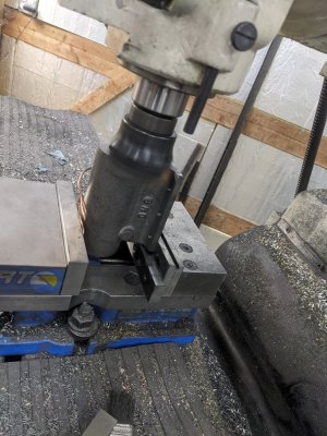
First, for these lead screw brackets, I flattened the outside to thickness:

PXL_20221013_202527347.jpg
Next, I found the center of the boss best I could, since the rest of the measurements are based on that:
PXL_20221013_203210423.jpg

Finally, I drilled and reamed the lead screw hole, and used the DRO for the mounting holes. The crossfeed mount is a little different (since a quadrant attaches to it), so those holes also got countersunk. One gotcha: 2 of them are 400 thou between the mount holes and leadscrews, the other is .325. the plans say match drill, so this is where I had to pay attention!PXL_20221013_203634420.jpg

After that, a test fit with these on the whole 3 axis setup:
PXL_20221013_212858502.jpg
PXL_20221013_212903072.jpg


I made a mandrel in the lathe with a 3/8" center to mount these so I could turn the OD. While drilling the end, I untwisted a #7 drill!
PXL_20221013_215927841.jpg

And here is the big one mounted on the mandrel. The OD mattered, and the depth didn't as much, but all are turned the same way. I used some bearing retainer loctite which stickied up just enough in 10 mins to hold the part still.

PXL_20221013_222858050.jpg

After doing all 3, here they are:
PXL_20221013_230612483.jpg

That was the end of yesterday!

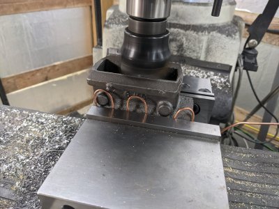
Today, I needed to do the back feature, where a thrust bearing is sandwiched between the mount and the lead screw shoulder. I was able to get them setup easily enough in the 4 jaw, and bored it out, a bit more than .300 deep, and .800 around for clearance. The stack up is only .265, so there is plenty of depth.
PXL_20221014_211007689.jpg

After all 3;
PXL_20221014_213711888.jpg

Then, I started on another part: the feed quadrant, which holds gears to power the gear through the cutter. First operation was a but precarious, but I was able to flatten it well enough. My casting was a bit pretzelly, so in the end I end up about 40 thou too thin, but hopefully that doesn't cause problems.PXL_20221014_215350166.jpg

Next, I flipped it over onto a fixture plate I made a while back, and milled the other side flat, moving clamps mid way through:
PXL_20221014_221357504.jpgPXL_20221014_222911004.jpg

I used the boring head to get a tight fit on the lead screw mount:
PXL_20221014_225556269.jpg

Finally, drilled the clamp hole, used the cut off wheel to make it a clamp, then went back and clearance drilled the top, then tapped:
PXL_20221014_231311669.jpg
PXL_20221014_231646041.jpg

And, done, clamped onto the mating part:PXL_20221014_231836618.jpg

And, that's it! All the castings in the "main tower", and all but 2 of the castings total! One of which I need a replacement, the other of which is another quadrant that attaches to that (so I have some adjustments I can use cutting it differently).

I'm on the fence whether I intend to drive the hour each way to pick up the replacement casting right away, or if I want to just start making the rest of the parts to assemble the main tower. What do you all think?
 
A little more work today! First, I bolted the L bracket to the frame, I had to widen one of the bolt holes in the bracket though, because my hand drilling wasn't accurate enough.

PXL_20221019_202321351.jpg

Next, I went to put the bottom slides dovetail in place, with the keystock in place. I discovered that I machined the keyslot wrong on the dovetailed piece! I put it in line with the bolt holes instead of about 63 thou further away.

I put this back on the mill and slotted the base bolt holes an additional 75 thou. They look a little oddly shaped because I didn't use the chamfer tool on it.
PXL_20221019_210030582.jpg

After that, it bolts on fine!
PXL_20221019_210604745.jpg

PXL_20221019_210610019.jpg
I actually then took it right off to put a little relief in all the slides, like this. The gib is held in place with the help of a pin, and this will let me be less accurate installing the pin to depth.
PXL_20221019_211742247.jpg

Speaking of gibs, time to make them! 1/2" by 1/8" brass cut into 6" pieces (quite a bit too long, but I'll cut them to size later), and a tilted mill head cleaned up the first side.
PXL_20221019_220519301.jpg

To get the other side, I milled a slightly thinner piece of aluminum with the same angle, then used it as a parallel. I ended up loctiting them together because I had a problem with them sliding.
PXL_20221019_222311341.jpg

PXL_20221019_223223894.jpg

Next, I had to drill the pin hole in the gib. After quite a few failed attempts, it took me too long to realize I already had a gib clamp! I ran the 3/16" endmill down the hole and cut it! You can see scars on this one from my failed attempts.

PXL_20221019_232136905.jpg
PXL_20221019_232141393.jpg

And that's it for today! I'll continue assembling the tower, making the parts needed to do so as I go!
 
Since my last post, I went and picked up a replacement for the casting I messed up.

AND, decided on my gear setup based on a hob I picked up on ebay:
16,20,24,25,28, 30,32,36,38,40,44,45,46,48,50,52,54,56,60,64,65,70,75, 80

From THERE, I did a bunch of programming (I'm a C++ Compiler engineer in my day job!) to try to figure out which gear sets I would need to get printed in order to be able to make 2 of each of those gears. I found a bit more than 400+ candidates and cut that list down as much as I could (limited valid gear trains by 'should mesh correctly' as well!), and have arbitrarily picked:

24 28 38 40 44 46 50 52

In doing the running, there are about 2.2 million combinations of 'gear trains' that result in one of the target gears (and are possible as best as I can tell!). I picked that set since it has sufficiently 'large' sets of gears that I think it can reach all the way across.

With those, I was able to come up with the attached document of 'how to get to all 24 gears' (and make a max of 2 of each!).

A gear-train has an 'input' gear, 2 'quadrant' gear-pairs, and an 'output' gear (plus there is a 20:1 reduction at the end!).

A Quadrant where both items of the 'pair' are the same are just a single-gear, and I represented them internally as a pair.

BUT 8 gears was the minimum I could find (though I THOUGHT there were some options for something like 16,16,16,20 when I was just getting started, but I cannot seem to reproduce that again!).
 

Attachments

  • GearSets.txt
    2.5 KB · Views: 4
Ah, woops! I found my 'bug' I guess on the doing-it-with-only-4-starters. It seems it requires duplicates! At one point when programming (it is a VERY large search space!), I was trying to limit the search space and ended up disallowing duplicate 3d printed gears.

BUT there are a whole bunch that apparently let me get away with only 4 printed gears!
 
So a few disorganized/all over the place sorta days, but not much to show of it.

I got all the lead screws cut, cleaned up, and turned down for a press fit extension. The extensions were then cut and drilled and press fit into place. 2 of the 3 got loctite, 1 I forgot.

I also got the replacement hob spindle housing casting, so today I did all the milling operations on that. I have to do the bores and area for the quadrant to mount, but I'm back to where I screwed it up last time.
 

Attachments

  • PXL_20221027_230256420.jpg
    PXL_20221027_230256420.jpg
    354.9 KB · Views: 21
  • PXL_20221027_221302871.jpg
    PXL_20221027_221302871.jpg
    476.1 KB · Views: 22
A little more work done... I had a few discouraging days of not getting much done, and having to restart/etc, so I had a bit of a "reset" day. Additionally, a bigger angle plate came, which means I can do the hobber body, which means I can get the 4 jaw off the lathe :)

First, I decided to drill/tap my handles. Work holding was awful, but it worked. I got these from LMS, since the handles specified in the plans no longer exist.

PXL_20221031_204535612.jpgPXL_20221031_205929999.jpg

The set screw is just an 8-32 I had left over from the gib screws, so I'll have to shorten them or buy shorter ones.

Next, I decided to continue working on the rest of the castings. I messed up this hob spindle housing last time, so I picked up a cheap shop made angle plate for this time.

PXL_20221101_202223802.jpg

I did some marking up, and got 4 holes drilled/tapped to use the mount holes to bolt it securely on the plate.
PXL_20221101_205519071.jpg

And here it is on the lathe. I had to bore the center to about 1.5":
PXL_20221101_210405706.jpg

Next, there is a second bore for the bearing on this side. Plans say slip fit, and I think I got it perfectly:
PXL_20221101_222253379.jpg

Finally, I had to cut the area for the quadrant clamp. Again, uneventful:
PXL_20221101_223709853.jpg

I have 2 things to do on the other side, which I might just do on the mill, but at least this setup is done.
 
Back
Top