[Mill] Finally got my first mill now I need help identifying it

I have the head ? Off what measurements would I need to take to find out what my tool holding options are
 
Table likely is a boring machine table (tenths). A milling table would move by thousands. Also the elongated Head and quill seem more related to drilling and boring operations.

Regarding work holding: easiest path is measure and research your existing collets. Then compare dims to a comprehensive collet ID chart. That will narrow down your workholding.

Also your likely initial machine components may fall between 1915 and late 30’s, because of the double pulley belt drive. The cobbled together electric drive is obviously recent- evidenced by the modern steel parts and welding technique. [Check the electric motor to determine its vintage...)

So maybe you’ll never pin point a specific “manufacturer”. All the parts seem to be assembled from a wide variety of original sources. maybe shop built for a specific purpose, then repowered for convenience.

Nevertheless, fun to chase down, if you have the time.
 
Table likely is a boring machine table (tenths). A milling table would move by thousands. Also the elongated Head and quill seem more related to drilling and boring operations.

Regarding work holding: easiest path is measure and research your existing collets. Then compare dims to a comprehensive collet ID chart. That will narrow down your workholding.

Also your likely initial machine components may fall between 1915 and late 30’s, because of the double pulley belt drive.

Nevertheless, fun to chase down, if you have the time.

Yeah , the early part of the 20th century was what I was thinking as well and I’ve been trying to use the pulley belt drive and the casting to find a match since they seem to have been made around the same time , as far as the newer drive and motor stuff the guy I bought it off of stated that originally the motor was down straight down from the back step pulley but that he cut that out and fabricated all that newer stuff above , I would assume the motor is of contemporary manufacture by its appearance but I’ll take a closer look , he also took a scrap lock out switch from where he worked to make the on and off. I went and got batteries for my calipers and came up with Dimensions for the collets , I’m thinking they’re homemade as well (surprise surprise !!)
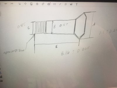
And they differ in length but the guy told me he thought they were 2c collets ... from my measurements they are closer to 4c , without a pitch gauge the threads appear to be 20tpi and with a 0.85 dia ~ 0.005
 
Here’s a quick sketch I made up on my tablet last night when I was measuring the collets , all dimensions are inches , I Was looking at a Hardinge table for collet dimensions but these fit none of them “exactly” so that’s why I wonder if the ID of my spindle bore is large enough could I get a drawbar (currently a draw tube) and r8 and see how they snug up ?
Let me be clear if my ignorance up til now has not I am completely green in the actual use of most of this stuff even if I’ve researched nothing compared to having the machine in hand and if trying to fit an r8 to this sounds idiotic just be gentle haha
image.jpg
 
It looks like a jig boring machine to me.

I know I can't be the only one on this entire forum that has done some make shift milling on a drill press and that machine is stouter than any drill press I have ever worked on. Sure, the spindle bearings might not be designed to handle the side loads of milling but does that really matter if you are able to accomplish what you want to do on it? I don't know the difference between tables ways on a jig boring machine vs a mill but if it works use it! For $150 I would have bought it and would have no reservations seeing what I can create with it.

I gasped at the butcher job that was done on the table, cutting it apart from the head/column casting but that does separate the column from that table which means they can be adjusted independently of each other which will allow you to tram the column to the table. It looks like you are going to need to tram the column with shims under the column and/or table. That will be a longer more laborious process than tramming a mill... but once it is done, it is done and should hold its tram just fine. Once the column is perpendicular to the table you can shim the spindle to be parallel to the column. I can't quite envision how you will adjust the spindle to the column... but you very well could find that you might not need to. I am confident something could be figured out if needed though.

My mill is worlds apart from my drill press... but you know what, I can still drill holes with my mill! Take her for a spin and see where you are at! ...then let us know what you figure out!

That is a beautiful piece of old iron!
 
Last edited:
Thanks and my thoughts were, I was approaching the point of diy mill because of costs .. as I’ve said my intentions are small beginner projects and for now I have no doubts this machine will handle them without a hitch I expect it will at very least rival a HF mini mill In some aspects and my hopes are to use this as a project to clean up and probably paint it with that ww2 olive drab paint and probably work my way up to taking the modern fabrication off the mill and add a more original looking motor mount system. Now as for the tramming that is something I would likely need you guys help with , specifically because I had assumed the table (although cut off at one point) was permanently attached where it is , however loosing it and fabricating a knee would definitely be something I’d like to do but tramming the head is probably the next task as of right now. If you could show me on my pictures where the shims should be placed to tram that would help a ton.

and if it is 3c collets how are my options ?

and as mentioned in the future with more experience and access to tools could the head and spindle be turned to fit better bearings like the tapered ones ( way in the future but just wondering )
 
It looks like the column (what I am calling the column is the whole upper end of the machine minus the table and table dove tail) is bolted to the base they fabricated with 4 bolts. I believe you should be able to alter the angle of the column to the base by loosening those 4 bolts then putting shim stock between the column and the fabricated base.

I believe you will want to make the dove tail ways of the column perpendicular to the table. So if you put a machinists square standing up on the table then attach a dial indicator to the head of the mill. You should adjust for minimal run-out up and down the machinists square when indexing the head up and down on the dovetail ways.
The procedure will be:
Check for run out,
loosen the 4 bolts,
add a minimal shim around 1 or 2 of the bolts,
tighten the 4 bolts back up,
repeat.
You will want to do this in both the X and Y directions. When you make a change in one direction you will also be making a minor change in the other direction so there is a lot of getting X dialed in, then getting Y dialed in, then having to adjust X again to compensate for the adjustment you made for Y.
Does my description make sense at all?

I was using a lock miter bit on my wood shaper and discovered the shaper spindle wasn't perpendicular to the table and I used this method to make it perpendicular. This took me the better part of a day but I had to put the shaper on its side, loosen the entire motor assembly from the table, add the shim, tighten it back up, then set the entire shaper back upright because the spindle would shift fractions between being on its side and upright. There was also a minor shift on my shaper when locking the spindle height in. This was a very minor shift but once I got the spindle perfectly perpendicular to the table when the spindle was locked the lock miters it cut in wood were a perfect fit.

Definitely test and see how perpendicular the head dove tail ways are to the table before making any changes or loosening those 4 bolts. If they are close to perpendicular I wouldn't change anything.

Once you have the dove tail ways on the head perpendicular to the table you will then want to attach the dial indicator to the end of the quill and see what the run-out is when indexing the quill up and down (I am assuming the quill moves independently from the head???). If the quill has a different run-out than the head... come back and we will figure something out on how to adjust it. :)

P.S. I think you will have a much nicer machine than a HF table mill!
 
Last edited:
Back
Top