G0704 CNC AC Servo Rebuild (Picture Heavy)

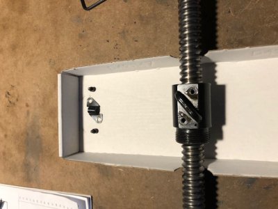
While I had the ballscrew out on the table, I figured I would try repacking it like I did with my X and Y axes. I had a cardboard lid with finger cutouts that made a great container to catch the balls.
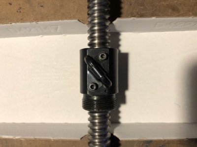
image018.jpg

Removing the ball track.

image019.jpg

I ended up removing all the balls, counting and measuring them individually. They were 0.1257" within a tenth or two. I decided to replace half of them with new balls that measured .1278" alternating every other ball.

This screw went from freewheeling loose to quite tight with this change. I can rotate the nut by hand, but not by pinching it between my thumb and index finger. This may shorten the life of the screw, but I know the motor (2.25 HP) won't have problems moving it. There is zero backlash in the screw now. If the screw gets worn, I will be fine replacing it with a better one.
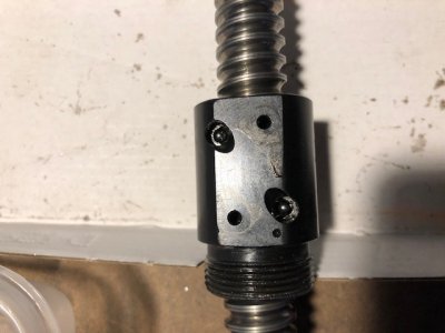
image020.jpg

The final balls (and a bit of extra space) are packed into the return tube with some bearing grease, then reassembled.
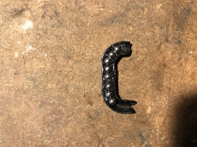
image021.jpg

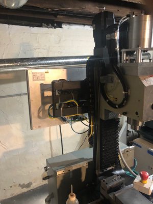
The ballnut and new block are reassembled onto the machine. Thanks to a new front facing access hole, the locking screw can be removed without removing the computer and monitor mount in the future.
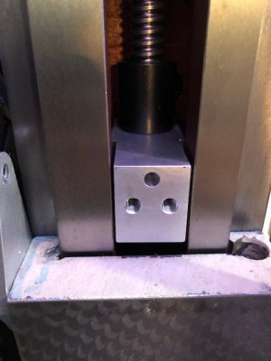
image022.jpg

New bolts from Home Depot (ugh so expensive) engage much more of the threaded hole and were torqued tight with Loctite. The other 4 bolts are longer than the stock bolts and hold down the Z axis bearing block at the top of the column.
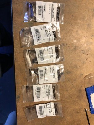
image023.jpg

Machine is coming back together. About 4 hours into it at this point.
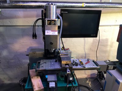
image024.jpg

New bolts ended up going here.

image025.jpg

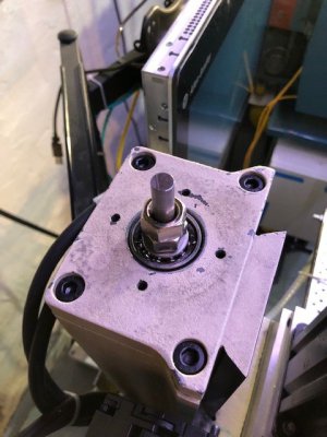
While I was working on everything, I decided to check on the state of the spindle belt. Absolutely zero dust since the first issues I had with it. Happy about that.
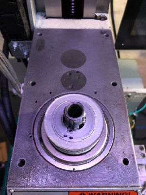
image026.jpg

A little black grease/oil is thrown around the wall of the spindle housing. Not sure where it is coming from. Shouldn't be a problem.
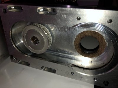
image027.jpg

Finally I retuned the Z axis servo. With the tighter screw, I could set the servo gains much higher than I could before without causing instability.

I started with the gains in the image below and got the gains after turning to:
-P = 400
-I = 125
-D = 0
-Kp = 23.00
-Kd = 0.00
-Kvff = 100
-Ki = 2.25

I was testing a 5" move at max accelerations and speed for the axis. Before tuning the motor would reach .008" position error during the very aggressive acceleration moves and I got that down to .0006" after tuning. During constant velocity, static positioning, or less aggressive moves (i.e. normal machining) then error was less than .0001" at the motor shaft. These values don't show mechanical errors of the machine, but it is a great starting point.

I do notice with the much tighter gains that the noise from each motor step (really the pulse from the ESS) is much louder than before. I may roll these tuning gains back just a touch purely to reduce this noise.
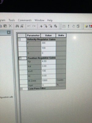
image029.jpg
 
Last night, I started working on the EMI/noise issue.

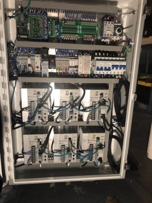
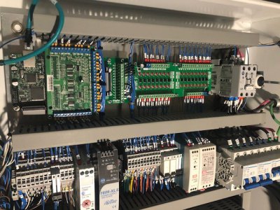
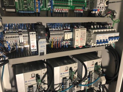
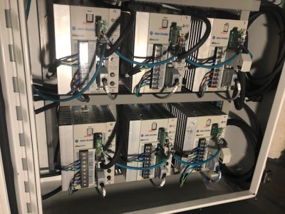
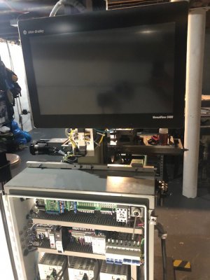
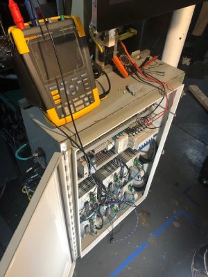
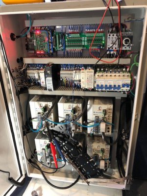
Here is the cabinet before I start tearing it apart ;)

32.jpg

33.jpg

34.jpg

35.jpg

The computer is able to flip backwards which is handy for troubleshooting.

36.jpg

37.jpg

I have my Fluke Scopemeter setup to measure the Step and Direction inputs right at the X axis drive connector.

39.jpg

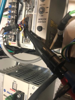
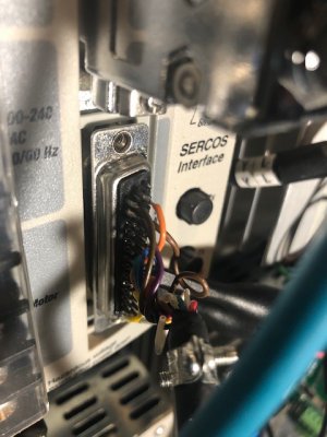
The leads are clamped directly to the pins on the DB44. Trying hard to make sure nothing shorts here.

40.jpg

The connector is pretty tight.

41.jpg

I hope to get a baseline for the level of noise tonight, then I can start working on reducing it.

My noise margin is 1.2VDC on the 5V input. I need to make sure that no noise spike ever gets above this level or it may be registered as a step by the drive (if the spike gets above 3.8VDC) or otherwise will cause a fault. Both are bad!
 
Nice work as usual. Regarding your thread indicator table, it's "probably" similar to my Grizzly G0709. Mine is numbered 1 - 4 at North, East, South and West with tick marks in between. Here's how mine works:

"ALL" means any number is good, no alignment required.
"1 - 4" means hit 1, 2, 3 or 4 or hit any of the numbers right on the number (guess you should be able to hit the ticks between also).
"1" means engage just on "1". Seems like in reality you could pick any number and continually hit that number.
"1 & 3" means numbers across from each other are good. So hit either 1 or 3, or hit 2 or 4.

I'd interpret your chart to mean:

"1" is pick a number and only hit that number
"1 - 4" means hit any of the numbers at 90's
"1 - 8" means hit any spot, no alignment needed
"1-3 / 2-4" means hit the same number or the number on the opposite side of the dial.

I'm guessing if it's crossed out or blank (like 4 1/2, 4 3/4, 5 1/2, etc.), you can't do the thread.

Might be worth chucking up a 1/2" - 13, 3/8" - 16, 5/16" - 18 and a 1/4" - 20 and set the QCGB to that particular thread. Set a threading tool close to the thread, then engage the half-nuts on a number. Adjust the cross feed and compound until you touch the thread (push the carriage to the right to take up the slop in the half-nuts) until your tool is square in the thread. Zero out your compound and cross feed. Back off the cross feed, disengage the half-nuts, and rotate the spindle by hand until the next target number comes up. Re-engage the half nuts and crank the cross feed back to zero. You should be aligned if I'm interpreting your table correctly.

More details (always more details . . . ). Naturally, doing the check above, your targets will change based on the thread. For the 1/2" - 13, you'll want to pick a number and stay with it ("1" on your chart). For the 3/8" - 16, try any spot on the dial. For the 5/16" - 18, hit the same number or the one on the opposite side. For the 1/4" - 20, hit just the whole numbers or whatever is 90 degrees apart.

Hope that helps! Really stinks to split a thread after all of the work to machine the part in the first place.

Bruce


Thanks for the feedback Bruce! It was sure frustrating but I ended up with a nice thread. I kept engaging on the "1" and it wasn't lining up right. I got frustrated and switch to "metric style" keeping the halfnuts engaged and reversing the lathe. It was a pain but it worked. When I have some free time I think I'll run some practice pieces and see what went wrong.
 
Wow, that should have worked fine. You'd have to suspect that either your lead screw is not imperial (probably 8 tpi) or something is wrong in your quadrant gears. I think I've read on this forum that guys have had a gear with the wrong number of teeth in either their quadrant or qcgb.

Fortunately you obviously have what it takes to figure it out pretty quickly.

Bruce
 
I've cut plenty of great threads with the lathe and never had issues with the threading dial or gearbox. My guess is that I was goofing and not closing the halfnuts completely.
 
I found the bore of the hole to be out of round by a little under a thou after boring on the mill. Not sure what that was about?

I think the sticky foam between the chuck jaws and the part contributed to the dimensional issue. Since one of the four faces was clamped without foam, that side didn't move when it went past the tool. The other three faces may have moved slightly under tool pressure. And I'm sure you didn't have the jaws clamped down super-tight as you were trying to avoid marring the part.

I'm guessing that if you mapped the hole at fairly tight increments it's not simply 'out of round' - but more egg-shaped, with the non-tape side being a bit larger than the other direction.

You might run a similar test again - same material and 3 of 4 jaws with foam tape. If you find my suspicions are correct you can switch to using copper sheet as jaw liners. If you need adhesive to keep the shims/liners in place a bit of spray adhesive would work well and be thin enough not to affect clamping pressures much.

Of course, some snap-on copper chuck jaw liners are always handy to have and aren't too difficult to make.

As an aside, if you find that your Z-axis is getting backlash in the future you might consider making a replacement nut block from steel. My first thought when I looked at it was 'why isn't he using steel thread inserts?' but the small holes are essentially in shear and you've increased the thread depth significantly. If it starts to stretch or deform from high Z loading (rapid reversing, heavy drilling, crashing) I don't think inserts would help much. I think the only answer would be a stronger base material. A chunk of cheap hot rolled steel would be great here.

Looking good, keep it up!
 
Spumco, The sheets I used are a hard phenolic with thin adhesive backing. I figured they'd be hard enough, but you are most likely correct. My confusion came about since the error in the hole came up before I made any cuts on the lathe. Just when centering it in the 4 jaw chuck. I wonder if it happened since there were 2 "strong" sides to the part and 2 "weak".

I would love to make copper jaws, but have never gotten around to it.

Steel definitely would have been the best choice here, but I still avoid cutting steel when possible on this machine, although maybe that's why I need to do it more. Also I had the aluminum on hand :)
 
I took a half day off work on Friday to work on getting the machine free of noise problems. Good news is that I was able to fix it! Here is the process.

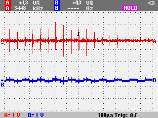
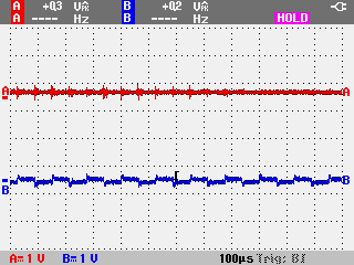
I started off by measuring the noise present at the X axis command input pins (Step = RED, Dir = BLUE). I added a grounded shield plate between the scope probes and the Y axis drive, since I was getting some noise artifacts from the drive output due to the proximity to the motor cable.

IMAGE012.png

59431956203__C5509561-F6DF-48AF-BFA3-C8E15CF538ED.JPG

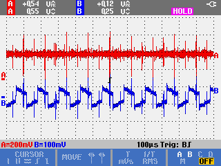
My starting values for noise were 1.3V at 16kHz on the Step signal and 0.3V at 8/16kHz on the Dir signal. These are the brief spikes in the scope image. The square wave visible on the Blue line are artifacts from the Y axis drive.

After running lots of tests, I figured out that the spindle drive was producing 75% of the total noise, regardless of if the motor was enabled or not. Here is a scope trend of the other 3 drives enabled, but the spindle drive powered off.

IMAGE011.png

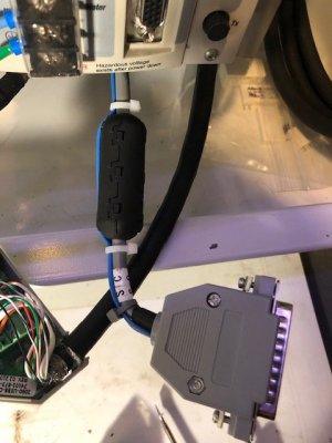
I decided to start by installing some broad spectrum ferrite cores on the control cables going to the drives, but these ferrites don't attenuate much noise at these low frequencies so they did very little. Still they will help with noise in general, so not a bad idea to install them.

IMG_6941.jpg

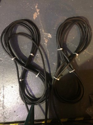
I also recoiled the long spindle cables into figure 8 patterns (really helps cut down coupled noise when coiling cables). They were stored inside the base of the mill again, but this time I added a big aluminum plate between them to help shield the feedback cable from emmissions.

IMG_6938.jpg

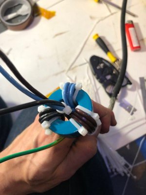
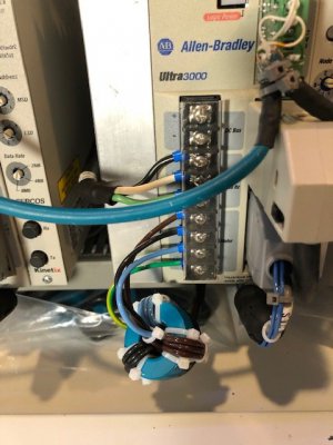
Next I added a pair of EMC ferrite toroid cores on the output of the spindle, hoping that the noise was coming from the cable. The blue core is a nanocrystaline core which is very effective from relative low frequencies up to 15MHz or so. The black core helps at even higher frequencies. I needed an extra 10 inches of cable stripped back to get this installed.

IMG_6947.jpg

IMG_6969.jpg

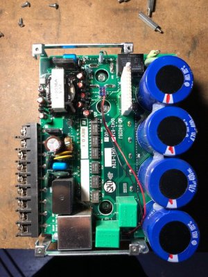
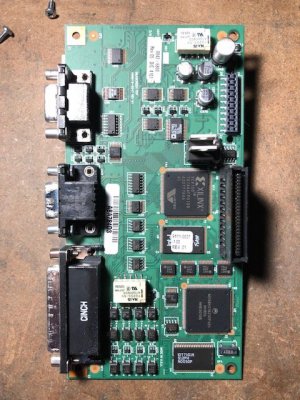
Finally I disassembled the drive itself looking for anything which might indicate a piece of failing hardware. At this point I was expecting to have to replace the drive (found a spares on ebay for $100-200). As I was finishing putting it together, I noticed that unlike the other 5 drives, the case of this one was entirely powder coated. I checked it with a meter and found it to be completely insulated from the rest of the drive. Huh... odd..

I took a knife and scraped away the paint by the mounting holes so that the case of the drive would get a good bond to ground. The spindle drive was a series A hardware build, while the other 5 I have are series B or C. They must have changed the design at some point to start using galvanized casings for the drives.

IMG_6949.jpg

IMG_6951.jpg

IMG_6952.jpg
After installing the drive again with these changes, I powered it on and took some new measurements. Note that the voltage scale has changed in this image from 1V per division on each signal to now 200mV on Step and 100mV on Dir.

IMAGE014.png

With all these changes, I now am getting 0.55V on Step and 0.12V on Dir. This is awesome! I am perfectly content with these numbers and after a few hours of testing I have gotten no faults or extra steps registered. I decided to be done at this point, but I can always go back and add additional EMC cores and filtering capacitors on the other drives if needed. In all I got a 65% reduction in the noise received on the X axis signals.

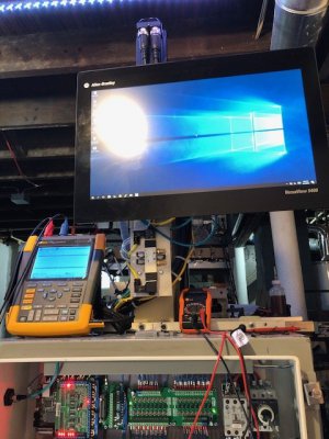
Here was my testing setup.
59431956746__69938480-B8C7-4B62-A497-4065744A70D9.JPG
 
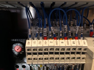
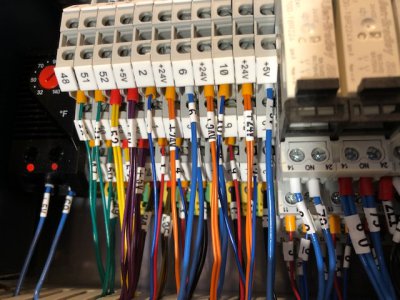
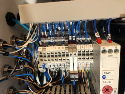
Since i had a little time left over yesterday, I went through and added terminal block labels on each connection. These are printed plastic tabs with a clip on the back. Ideally you install these BEFORE attaching the wires, however I had to do it the other way around... :rolleyes:

This was a bit like playing the game operation. I had a small screw driver covered in tape that I would stick a label to. I then reached all the way to the back of the panel to snap it into place. If I bumped a wire, the label would fall off and I'd have to go fish it out.

59432639292__C0E04F88-3213-4706-B473-B16E27780289.JPG

59432640166__A9ABE3C3-D765-472B-A61D-DCCD6486C7F1.JPG

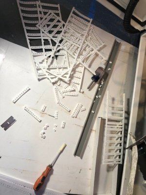
IMG_6962.jpg

Here was my pile of labels! What a pain.

IMG_6959.jpg

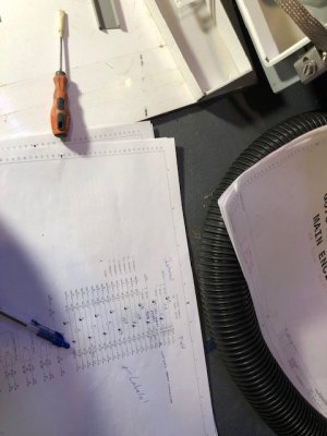
This also provided a good opportunity for me to go through a double check all the wiring. I have a half complete set of electrical schematics which I hope to finish up and match the actual panel.

IMG_6960.jpg

I'm happy with the progress. I really need to come up with a project so I can use the machine!:D
 
Back
Top