G0704 CNC AC Servo Rebuild (Picture Heavy)

I just got permission from a past customer to share some pictures of a job I did for them.

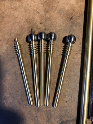
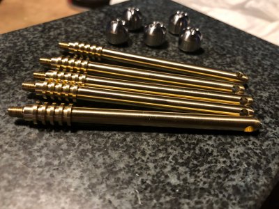
5 Assemblies, one part was free machining brass, one part was 316 Stainless.

The slender part was cut with a single pass from 7/16" barstock and finished with fine sandpaper for finish and to dial in the final size evenly along the length of the part. The full radius on the small end was cut with a form tool. Tolerance was +/- 0.003" all over. I had a bit of difficulty holding tolerance on the overall length and diameter of the slender part. The second operation used my CNC as a lathe with tools ganged in the vise. The profile was finished using a sharp corner CCGX insert and the grooves machined with a Thinbit by Big Kaiser tool swapping the insert between sizes mid program. The small M3.5x0.6 thread was cut with a die. The cross hole was drilled on the CNC in a third operation.
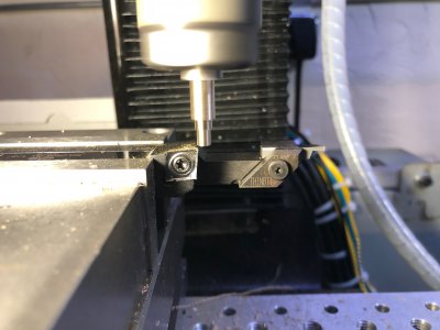
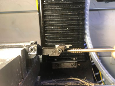
image001.jpg

image004.jpg

The stainless "ball" was roughed from 1/2" barstock on the lathe, the smaller radius cut with a form tool, center hole drilled with a carbide drill, and finally tapped M3.5x0.6. The stock was parted off on the lathe, threaded onto a fixture mounted in a TTS toolholder, and the larger profile was cut on the CNC. The CCGX insert held up to the stainless quite well and left a beautiful surface finish. The part was fixtured for a 3rd operation on the CNC were the 3 dimples were drilled with a ball endmill.
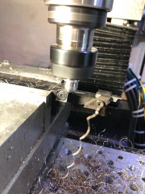
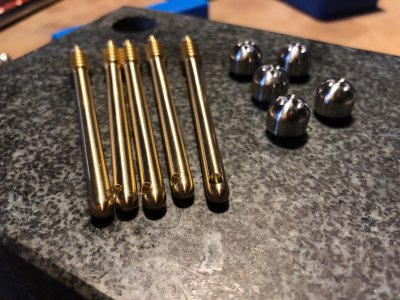
image007.jpg


image016.jpg

image011.jpg

image015.jpg

Parts were cleaned and deburred before shipping them off.

I had a lot of fun with this job and have plans to keep working with this customer again in the future.

Mike
 
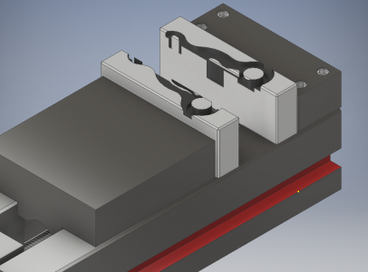
Going to modify the soft jaw design a bit based on feedback above.

This time, the jaws are placed 0.25" closer together, creating engagement on all features of the first side of the part.

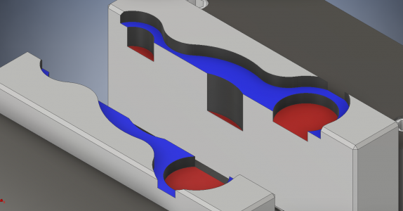
Soft jaws immediately after subtracting the part to be gripped.

1576288669812.png

And after removing the unnecessary remnants of the boolean operation.

1576288913248.png

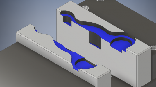
Surfaces highlighted in red are designed to not touch the part and were cut 0.015" deeper than the geometry that would touch it. Blue faces are designed to support the part in the Z direction.

1576289106333.png

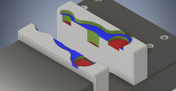
Surfaces in green were expanded outwards by 0.003" to allow clearance for the part to fit into the jaws. I felt that the original 0.005" might have been too loose, however I can adjust this after I have cut the jaws and test fit the part.

1576289440034.png

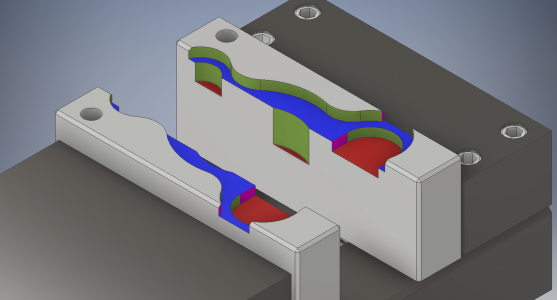
Finally the faces in purple are cut to allow the part to come loose from the jaws as the vise opens and to remove some razor sharp edges. The two holes are 1/4" reamed holes. This would allow the jaws to be realigned in the future with a pair of dowel pins and an indicator. The hole on the fixed jaw will also serve as the zero location for the G-code.

1576289799741.png

I plan on cutting this tomorrow and starting on the programming of the second side of this part.

Mike
 
looks well though out. Looking forward to seeing how it works out. Seems like you will have enough surface area in contact to keep the part from popping out.
 
I've had some success holding slippery parts (UHMW, PVC, Delrin) by scuffing the soft jaws with some fine sandpaper. Not much, just enough to take the gloss off. Seems to bite a bit better.

Other things to try:
1. Undercut the bottom sides with a dovetail cutter (like a grinding relief), or use a small threadmill (or lathe threading bar) to create serrations in the clamping surfaces. Once serrated, go back over the surface with a final contour spring pass to get rid of any burrs that may mar the clamped surface. The bottom relief keeps it from squishing out.
2. Degrease the jaws & stock with alcohol so any coolant/mold release is off the surfaces
3. Light coating of spray adhesive on the part before putting it in the vise. The adhesive should only be put on one surface (part only) as if you do it on the vise jaws and part they're likely to bond pretty firmly. I haven't found any dimensional issues using a very light spray - and plastics aren't exactly dimensionally stable to begin with. Of course test the adhesive to make sure the propellant/solvent doesn't attack the plastic.
 
I never thought of Spray Adhesive. Great idea.
 
@spumco, Thanks for the tips. I ended up making the soft jaws before I read this, but I'll remember for next time.

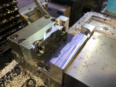
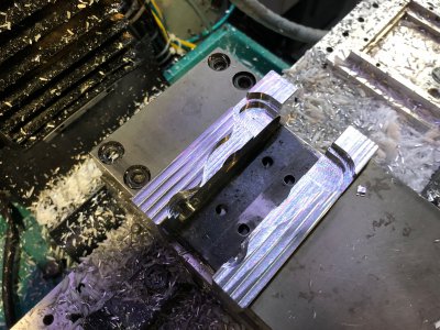
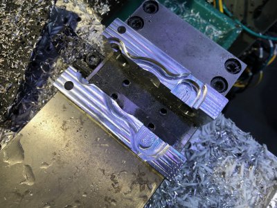
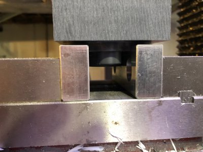
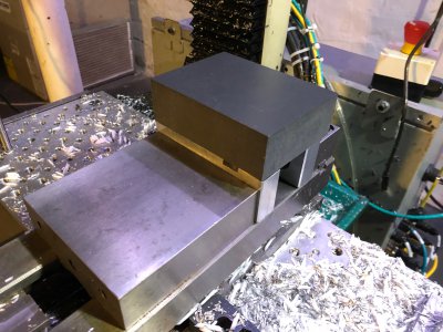
I machined the soft jaws while clamping on some parallels that spaced the jaws exactly as they were in my CAD model. Also helped deal with any jaw lift.

image001.jpg

image002.jpg


image005.jpg

The part dropped into the features perfectly and clamped extremely firmly once the parallels were removed :rolleyes:

image008.jpg

image009.jpg

image010.jpg
 
Programming the second side of this part proved to take a lot more effort than expected. About 3 hours.

Operation 1: Facing w/ 0.375 endmill
Operation 2: Dynamic Roughing outside profile
Operation 3: Dynamic Roughing Interior Pocket
Operation 4: Dynamic facing of island
Operation 5: Helical boring of central bore
Operation 6: Dynamic Rest Machining of central pocket, 0.250" endmill
Operation 7: Dynamic Roughing of interior pocket
Operation 8: Taper finishing of walls, 5 deg taper endmill, 3 flute
Operation 9: Dynamic Rest machining of all features 5/32" endmill
Operation 10: Finishing contours
Operation 11: Chamfer

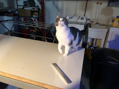
Kate hung out with me nearly the whole time the machine was running

image001 (2).jpg

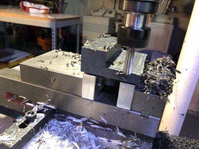
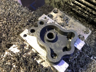
Facing cut, heavy stock removal. I'm noticing that the mill is chattering a lot when climb cutting along the X axis, conventional is fine. Thinking I might have a lot of backlash on the X screw. Thoughts?

image002 (2).jpg

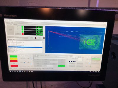
Mach 4 running the part

image003 (2).jpg

After Dynamic roughing

image005 (2).jpg

Making an absolute mess.

image006 (2).jpg

After Taper finishing of the walls, don't know why the image wants to flip on its side.

image007 (2).jpg+

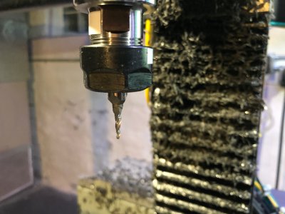
The HSS taper endmill.

image008 (2).jpg

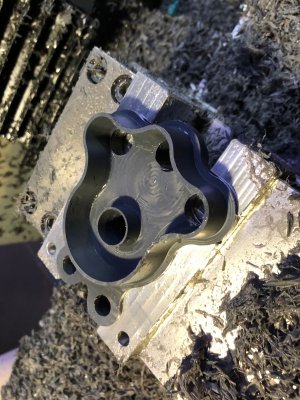
After the 1/4 and 5/32 cutters.

image009 (2).jpg

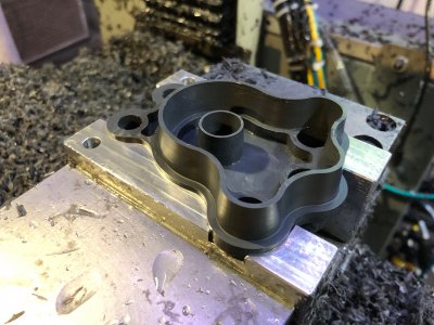
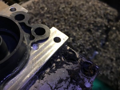
Almost had it perfect, but a little mistake in programming called H318 for T03. This crashed the head straight into the jaws. Luckily, the spindle drive locked up, faulted, and shut down the system. There was no damage besides the pock mark in the jaw and a blemish on the part. Tool didn't break. I will have to make another part so it can be perfect.

image010 (2).jpg

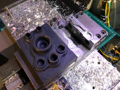
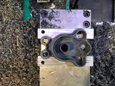
"Finished" part, minus the chamfers and my oops mark!

image011.jpg
 
I have always had the climb-cut-on-X-chatter- while-roughing issue.

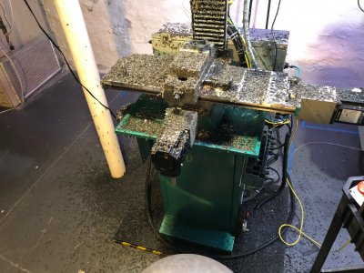
I've pushed/pulled on the table in every direction and will get a few thou movement in Y, which goes away when the Y gib is locked. I suspect the ball nut mount came loose and the movement is whatever bolt clearance there is?

Not sure, but I plan to take it apart soon to diagnose.

The part looks good! You can also play with the Horizontal Area toolpath for finishing floors. Many times you can select the entire solid and it will do what is possible with the selected tool, then maybe unselect the features you need more control over and address those in a different OP. I don't use it much, but it sure is handy sometimes.
 
Here is an old video. The chatter is heavier when moving in X+. It has always done this to some degree, but did progressively get worse.


I eventually got tired of this and reposted using conventional direction just to get parts done. I am able to feed way faster that way, should have done it sooner.

I still have a back log of work, but coming to the end of it. Can't wait to get in there to fix it.
 
As you suspect, chatter is likely one of the following:
Ballscrew nut to saddle
Ballscrew housing bearing
Ballscrew bearing housing to table
Y-axis gib loose(ish). That's the easiest to check & fix.

In addition, you're using the TTS which likes to chatter with long gauge lengths. Crank down on the drawbar until your PDB just barely releases, stick that roughing end mill in a shortie setscrew holder instead of the collet and go to town.

Hog the plastic with a 1/2" corncob once you double-check your backlash suspects. With that spindle motor you should be making chunks.

And 3 hours to program? That's fast for someone who doesn't do it for a living. Seriously.

Nice job on the part. Learn from the 'oops' and have another go at it.
 
Back
Top