-
Welcome back Guest! Did you know you can mentor other members here at H-M? If not, please check out our Relaunch of Hobby Machinist Mentoring Program!
You are using an out of date browser. It may not display this or other websites correctly.
You should upgrade or use an alternative browser.
You should upgrade or use an alternative browser.
Greg's Logan 820 Restoration
- Thread starter gjmontll
- Start date
Re: Greg's Logan 820 Restoration - Initial Alignment Check
Prior to overhaul of the headstock, and total dissassembly of the bed, countershaft/motor assembly and the legs, I want to know how well it is currently aligned, and how level it is before I add the leveling legs. BTW, in my last posting, about my leveler legs, for some reason, the picture did not get correctly inserted, so here it is. [I hope my pictures attach properly this time.]
Hockey Puck Leveler Feet
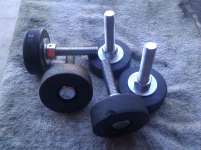
On Sunday, I first checked the countershaft and its bushings. I was suspecting them to be very worn, just as the apron and gearbox shafts have been. To my surprise, I was not able to feel any play in the countershaft. I'm guessing it has already been replaced sometime over the years. Maybe a closer look when I take it apart will change my mind, but for now, it's good to go.
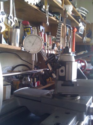
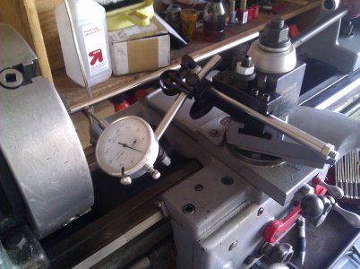
When I first started my machining hobby, five years ago, I became aware of the "Rollie's Dad's Method of Lathe Alignment (RDM)." But I never used it on my first lathe, an Atlas 618. It turned out to be less complex than I'd thought it was. Using a shaft cannibalized from a junk printer as my test bar, I took the horizontal and vertical measurements at 1" from the chuck, and then again at the 7" point.
RDM Vertical and Horizontal Measurement Setups
 s
s
RDM Results
Vertical, over the 6" range, I measured a 0.0027" difference at the two stations, or 0.0054 per foot, the right side is low.
Horizontally, it was 0.0018 difference, 0.0036 per foot, skewed toward the back.
Given that I never leveled the lathe, I suppose that is not too bad, is it? I wonder how much of the errors are due to bed twist rather than headstock alignment. See below....
Level Check
So how unlevel is the lathe currently, just sitting on my garage floor? Using a machinist's level, I checked across the ways next to the spindle, and at the tailstock end, about 3 feet away. Here were my setups. Note, the 2-foot carpenter's level is just used as a bridge over the saddle, not as a level.
Longitudinal and Cross-bed Level Checks
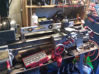
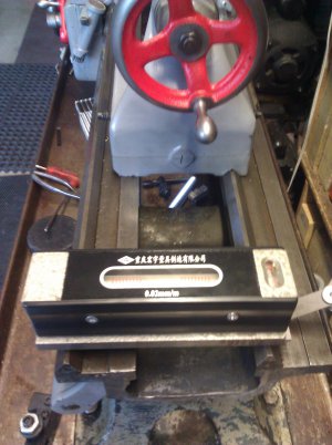
Longitudinally, the tailstock end is about 0.288 lower, over that 2 foot span. Given that garage floors are supposed to slope toward the door at somewhere around 1/8" and 1/4" per foot, that is just about right. Across the ways, measuring across the vee's (a 5" span), at the chuck end, I got about 0.026" down slope, from front to back, 0.062" per foot. At the tailstock end, 0.018" down, front to back, or 0.043" per foot.
These measurements suggest there is 0.019 twist along the 3 foot bed. Unfortunately, it is is the wrong direction to be causing the RDM horizontal skew.
Again, this was my first effort at measuring alignment and levelness, as a benchmark before I breakdown the headstock. Have I made any significant mistakes that invalidate my analysis? Or that at least need to be resolved before I actually do the alignment.
Greg


Prior to overhaul of the headstock, and total dissassembly of the bed, countershaft/motor assembly and the legs, I want to know how well it is currently aligned, and how level it is before I add the leveling legs. BTW, in my last posting, about my leveler legs, for some reason, the picture did not get correctly inserted, so here it is. [I hope my pictures attach properly this time.]
Hockey Puck Leveler Feet

On Sunday, I first checked the countershaft and its bushings. I was suspecting them to be very worn, just as the apron and gearbox shafts have been. To my surprise, I was not able to feel any play in the countershaft. I'm guessing it has already been replaced sometime over the years. Maybe a closer look when I take it apart will change my mind, but for now, it's good to go.
When I first started my machining hobby, five years ago, I became aware of the "Rollie's Dad's Method of Lathe Alignment (RDM)." But I never used it on my first lathe, an Atlas 618. It turned out to be less complex than I'd thought it was. Using a shaft cannibalized from a junk printer as my test bar, I took the horizontal and vertical measurements at 1" from the chuck, and then again at the 7" point.
RDM Vertical and Horizontal Measurement Setups

 s
sRDM Results
Vertical, over the 6" range, I measured a 0.0027" difference at the two stations, or 0.0054 per foot, the right side is low.
Horizontally, it was 0.0018 difference, 0.0036 per foot, skewed toward the back.
Given that I never leveled the lathe, I suppose that is not too bad, is it? I wonder how much of the errors are due to bed twist rather than headstock alignment. See below....
Level Check
So how unlevel is the lathe currently, just sitting on my garage floor? Using a machinist's level, I checked across the ways next to the spindle, and at the tailstock end, about 3 feet away. Here were my setups. Note, the 2-foot carpenter's level is just used as a bridge over the saddle, not as a level.
Longitudinal and Cross-bed Level Checks


Longitudinally, the tailstock end is about 0.288 lower, over that 2 foot span. Given that garage floors are supposed to slope toward the door at somewhere around 1/8" and 1/4" per foot, that is just about right. Across the ways, measuring across the vee's (a 5" span), at the chuck end, I got about 0.026" down slope, from front to back, 0.062" per foot. At the tailstock end, 0.018" down, front to back, or 0.043" per foot.
These measurements suggest there is 0.019 twist along the 3 foot bed. Unfortunately, it is is the wrong direction to be causing the RDM horizontal skew.
Again, this was my first effort at measuring alignment and levelness, as a benchmark before I breakdown the headstock. Have I made any significant mistakes that invalidate my analysis? Or that at least need to be resolved before I actually do the alignment.
Greg


Greg, I don't remember what the Rollies Dads Method entails, but I've always thought the proof was in the pudding. I start by leveling a machine across the ways ( I don't pay much attention to level from end to end) and then checking/adjusting the height of the tailstock. With a bar set up between centers I take a few cuts and adjust the tailstock side to side until I get the least amount of taper as possible. On an older machine like yours, if I can stay under .001 taper over 8 - 12", I consider it good enough. I guess at that point you could twist the bed one way or the other to try to eliminate the taper, but if you have wear in your ways and saddle it's not likely that your going to remove the taper in all areas of the bed. Everybody has their own preference for setting up and leveling their machine. I think that the fact that you're doing it puts you ahead of a lot of lathe owners.
Chuck
Chuck
- Joined
- Nov 22, 2010
- Messages
- 371
Re: Greg's Logan 820 Restoration - Apron Teardown
You might want to consider Rusteolum "Burgundy" as an alternative to the red you show in your photos. A bit more "antique Engine" looking. To my untrained eye
You might want to consider Rusteolum "Burgundy" as an alternative to the red you show in your photos. A bit more "antique Engine" looking. To my untrained eye
Re: Greg's Logan 820 Restoration - Countershaft teardown
It's been a while (6 weeks) since I wrote up my progress, but there has been nothing too remarkable. I've been stripping and repainting the big parts in the drive unit, and that is still ongoing. So far, I'm done with the countershaft bracket, drive box, floor stand, and motor bracket.
Back in December I said, ".., I first checked the countershaft and its bushings. I was suspecting them to be very worn, just as the apron and gearbox shafts have been. To my surprise, I was not able to feel any play in the countershaft. I'm guessing it has already been replaced sometime over the years. Maybe a closer look when I take it apart will change my mind, but for now, it's good to go.
Yeah, well now that I got the shaft and bearings torn down, it's not as pristine as it had seemed! Here's the LA-317 shaft. Or is it? It is a plain 3/4" shaft, about 11 5/8" long and has no flats for the five setscrews that bear against it.
Can anyone tell me if the real Logan LA-317 part has any flats?
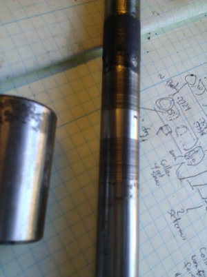
This 3/4"shaft runs in 4 bronze bushings, the worn spots on the shaft are worn between .004 and .013". And the bushings are worn at least .008 to .010". So while I didn't feel the play while everything was in place, on the workbench, the wear is easily felt. [I don't remember if I removed the motor belt when I was checking, maybe that would have been revealing.
I will make a shaft and mill the flats for setscrews, and get some new bushings.
My motor is an Atlas Press Co, Super Power 3/4 hp motor. I will replace the wiring from the motor to the switch and from the switch to the plug. Besides exterior cleanup and oiling the (ball) bearings, is there anything else that should be done? Or that shouldn't be done? I don't see any brushes. Are there any or are they hidden?
Back to work,
Greg

It's been a while (6 weeks) since I wrote up my progress, but there has been nothing too remarkable. I've been stripping and repainting the big parts in the drive unit, and that is still ongoing. So far, I'm done with the countershaft bracket, drive box, floor stand, and motor bracket.
Back in December I said, ".., I first checked the countershaft and its bushings. I was suspecting them to be very worn, just as the apron and gearbox shafts have been. To my surprise, I was not able to feel any play in the countershaft. I'm guessing it has already been replaced sometime over the years. Maybe a closer look when I take it apart will change my mind, but for now, it's good to go.
Yeah, well now that I got the shaft and bearings torn down, it's not as pristine as it had seemed! Here's the LA-317 shaft. Or is it? It is a plain 3/4" shaft, about 11 5/8" long and has no flats for the five setscrews that bear against it.
Can anyone tell me if the real Logan LA-317 part has any flats?

This 3/4"shaft runs in 4 bronze bushings, the worn spots on the shaft are worn between .004 and .013". And the bushings are worn at least .008 to .010". So while I didn't feel the play while everything was in place, on the workbench, the wear is easily felt. [I don't remember if I removed the motor belt when I was checking, maybe that would have been revealing.
I will make a shaft and mill the flats for setscrews, and get some new bushings.
My motor is an Atlas Press Co, Super Power 3/4 hp motor. I will replace the wiring from the motor to the switch and from the switch to the plug. Besides exterior cleanup and oiling the (ball) bearings, is there anything else that should be done? Or that shouldn't be done? I don't see any brushes. Are there any or are they hidden?
Back to work,
Greg

- Joined
- Jul 27, 2013
- Messages
- 295
Hey;
Yours is not worn bad at all. Check out my rebuild thread for some real wear! I used a regular piece of high precision ground drill rod and oilites from McMaster Carr. No flats originally and I didn't add any to mine. Don't know nuthin from electrics.
Yours is not worn bad at all. Check out my rebuild thread for some real wear! I used a regular piece of high precision ground drill rod and oilites from McMaster Carr. No flats originally and I didn't add any to mine. Don't know nuthin from electrics.
Re: Greg's Logan 820 Restoration - Reply to Redlineman on Countershafts, Rubber Bushings
Redlineman,
Countershaft
Looking at the picture in your "Redlineman's Logan 200 Rescue thread", I see you were not kidding about the shaft being badly worn. It also looks like your pulley was slipping, and the setscrews scarred all the way around the shaft. It doesn't look like mine was slipping, but as I said, I plan to put some flats for the setscrews. I already have some 3/4" rod on hand (both drill rod and plain) so while I have it apart, I'm going to replace the shaft and bushings.
Rubber Bushings?
You have recently been talking about the rubber bushings. and I've been thinking, what rubber bushings? I haven't seen any. But now, looking at the parts catalog, I do see where the LA-658 bushings are supposed to be, in the connection 'tween the drive box and the headstock. Somebody has modified mine. I have a steel rod with a 5/16" hole that connects the two LA-657 hinge brackets. One long 5/16" pin is used to make the connection, rather than the two LA-372 pins. I'll get some pictures...
Greg
Re: Greg's Logan 820 Restoration - Non-standard bracket on headstock
As I mentioned in my last posting, my Logan 820 does not have any bushings in the bracket that connects the drive box to the headstock. Sometime in the past 70 years, someone substituted a 6" piece of aluminum rod with a 3/8" through-hole as shown here:
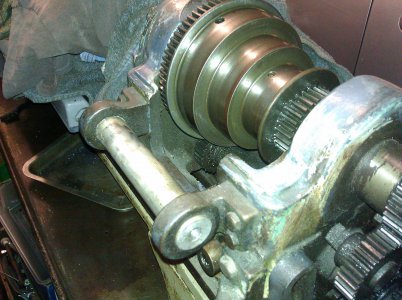
And instead of short pins on each side, to connect the drive box; my machine has a long steel rod (10.5 x 3/8") that runs all the way through.
Other than as an expedient repair, does anyone have an idea why this may have been done. It seems to work fine. For now, I plan to leave it this way until I make or get some bushings. I wonder how much difference it would make, vibration-wise? You may remember I've made hockey puck leveling feet, hopefully they will provide some dampening too. And I think have one puck left over. Once the lathe is operational again, I could machine bushings from that, as Redlineman discusses in his thread.
Greg

As I mentioned in my last posting, my Logan 820 does not have any bushings in the bracket that connects the drive box to the headstock. Sometime in the past 70 years, someone substituted a 6" piece of aluminum rod with a 3/8" through-hole as shown here:

And instead of short pins on each side, to connect the drive box; my machine has a long steel rod (10.5 x 3/8") that runs all the way through.
Other than as an expedient repair, does anyone have an idea why this may have been done. It seems to work fine. For now, I plan to leave it this way until I make or get some bushings. I wonder how much difference it would make, vibration-wise? You may remember I've made hockey puck leveling feet, hopefully they will provide some dampening too. And I think have one puck left over. Once the lathe is operational again, I could machine bushings from that, as Redlineman discusses in his thread.
Greg

- Joined
- Jul 27, 2013
- Messages
- 295
Holy Schmoley;
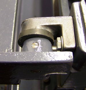
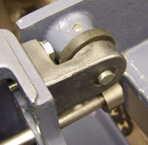
That really had me thrown for a loop. It just looks so impossibly massive. Then I noticed the essential difference. The 820 obviously must have had a much larger OD bushing of whatever sort. You can see the 820 bracket curves out for a much larger bushing hole where the 200 bracket (which uses a .375 pin) below comes straight off the headstock. Somebody either lost, broke, or wore out your original hardware, or must not have been impressed with it. It is kind of odd having that whole big heavy assembly standing on a peg, hanging off the back from a couple of little pins. One of my bushings is blown apart, so the thing really flops around.
That really had me thrown for a loop. It just looks so impossibly massive. Then I noticed the essential difference. The 820 obviously must have had a much larger OD bushing of whatever sort. You can see the 820 bracket curves out for a much larger bushing hole where the 200 bracket (which uses a .375 pin) below comes straight off the headstock. Somebody either lost, broke, or wore out your original hardware, or must not have been impressed with it. It is kind of odd having that whole big heavy assembly standing on a peg, hanging off the back from a couple of little pins. One of my bushings is blown apart, so the thing really flops around.


Re: Greg's Logan 820 Restoration : Drive Unit Overhaul
For the past few months, I've been overhauling the drive unit. As I said back in February, there was a little bit of wear on the countershaft and its bushings in the drive box. I made a new shaft and got new bronze bushings.
Here is the drive box, after repainting, with the new shaft/bushings.
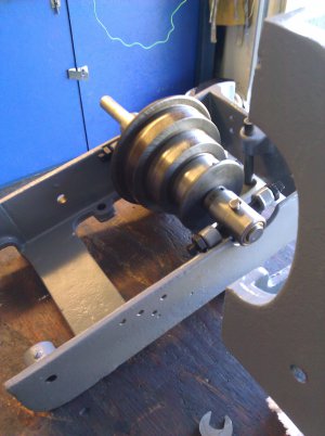
Most of time has been spent removing old paint and repainting each of the pieces, and the drive unit has several large pieces. Not having a lot of extra room in my garage/shop/paint shop, it has been one or two pieces at a time, laid on cardboard, under where I park my car. So it's spray some paint, park the car for the night, next day or so, turn the piece over and repeat for primer and top coats.
The motor is an Atlas Press Company 3/4 hp "Super Power" that was dirty but in good shape. I took it apart for a good cleaning, not entirely disassembled but took off the end bells and the rotor. There was some swarf and other crud inside, but obviously not where it could short out anything -- that's why I took it apart rather than just blow it out with the air hose. Shaft and bearings were fine. I replaced the cord and plug too.
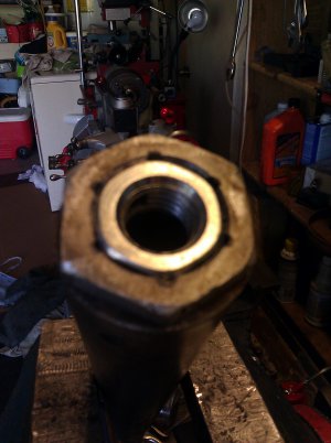
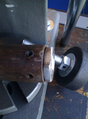
Because I am adding hockey puck leveling feet to the lathe, I also needed to add one to the drive unit's "pegleg". I discovered that the pegleg is non-standard, it's just a piece of pipe I needed to adapt it for the 5/8" thread leveler bolt.Here is the detail on that. The first image below shows a cast iron pipe fitting with 6 milled grooves that allowed a 5/8" bolt to be very tightly pressed in. Then (see 2nd image) the cast iron piece is pressed into the leg and secured with a pair of set screws. The actual hockey puck foot is there waiting for assembly.
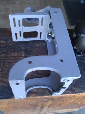
Putting the drive unit back together was an exercise in wrestling awkward heavy pieces.
Step one: Floor stand and motor mount
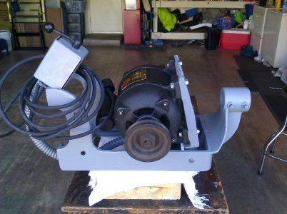
Step 2: Mount the motor. Note: I should have taken measurements of exactly how the motor sat in its alignment slots. I had to mess around getting the motor pulley properly aligned with the pulley on the countershaft.
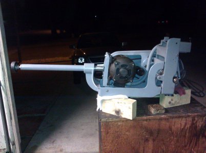
Some time later, it's done (except for the lid), here's the right side view.
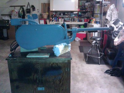
And the left side. I guess it was the camera flash that makes this look different, but it is the same gray as in the other images. As I've said, my shop is in the garage/laundry room running along half a wall. The mill and lathe are under their covers and the workbench is out of sight immediately to the right of the hockey puck foot.
Now I will put the assembled drive unit aside and start on the next major subassembly. That will be the headstock. While the headstock is off, I will repaint the bed, tray, and legs. Then put it all back together, aligned it, and I will be done.
Note: I have already removed the headstock and disassembled it. I will post on that within a day or so. It was interesting.
Greg


For the past few months, I've been overhauling the drive unit. As I said back in February, there was a little bit of wear on the countershaft and its bushings in the drive box. I made a new shaft and got new bronze bushings.
Here is the drive box, after repainting, with the new shaft/bushings.

Most of time has been spent removing old paint and repainting each of the pieces, and the drive unit has several large pieces. Not having a lot of extra room in my garage/shop/paint shop, it has been one or two pieces at a time, laid on cardboard, under where I park my car. So it's spray some paint, park the car for the night, next day or so, turn the piece over and repeat for primer and top coats.
The motor is an Atlas Press Company 3/4 hp "Super Power" that was dirty but in good shape. I took it apart for a good cleaning, not entirely disassembled but took off the end bells and the rotor. There was some swarf and other crud inside, but obviously not where it could short out anything -- that's why I took it apart rather than just blow it out with the air hose. Shaft and bearings were fine. I replaced the cord and plug too.
Because I am adding hockey puck leveling feet to the lathe, I also needed to add one to the drive unit's "pegleg". I discovered that the pegleg is non-standard, it's just a piece of pipe I needed to adapt it for the 5/8" thread leveler bolt.Here is the detail on that. The first image below shows a cast iron pipe fitting with 6 milled grooves that allowed a 5/8" bolt to be very tightly pressed in. Then (see 2nd image) the cast iron piece is pressed into the leg and secured with a pair of set screws. The actual hockey puck foot is there waiting for assembly.


Putting the drive unit back together was an exercise in wrestling awkward heavy pieces.
Step one: Floor stand and motor mount

Step 2: Mount the motor. Note: I should have taken measurements of exactly how the motor sat in its alignment slots. I had to mess around getting the motor pulley properly aligned with the pulley on the countershaft.

Some time later, it's done (except for the lid), here's the right side view.

And the left side. I guess it was the camera flash that makes this look different, but it is the same gray as in the other images. As I've said, my shop is in the garage/laundry room running along half a wall. The mill and lathe are under their covers and the workbench is out of sight immediately to the right of the hockey puck foot.

Now I will put the assembled drive unit aside and start on the next major subassembly. That will be the headstock. While the headstock is off, I will repaint the bed, tray, and legs. Then put it all back together, aligned it, and I will be done.
Note: I have already removed the headstock and disassembled it. I will post on that within a day or so. It was interesting.
Greg


