Group Project: Dividing Head - Organization and Design

I was thinking on the same lines. It would be possible to make a new hobb from a single pointed gear shaft.

Looking very complex!
Single pointing the worm will be challenging on a light machine due to chatter. Do a test run first maybe? As I recall Erich has a pretty robust machine so it might be fine. What about silver soldering a section of worm over a shaft? If the fit was tight it would be very concentric and a solid joint.
I hope you guys don't mind if I play "devils advocate" and try to find issues with the design. I think that could be helpful before parts are made.
Robert

Dont mind at all, Just bear in mind that there are compromises made to accommodate the capabilities of the individuals in the project and to keep cost down.
 
  • Like
Reactions: rwm
I was thinking on the same lines. It would be possible to make a new hobb from a single pointed gear shaft.


Dont mind at all, Just bear in mind that there are compromises made to accommodate the capabilities of the individuals in the project and to keep cost down.
I figured I would just machine the worm gear to the same dimensions as the hobb...
 
Do you guys still want sub-forums? I think this is a great idea BTW @ErichKeane.


Sent from my iPhone using Tapatalk
 
I can see pros and cons to having sub forums for this. I guess I am not sure what you are suggesting for us to do with the sub forums?

PS, I have all the part drawings down on paper so to speak. I am now teaching myself how to do the assembly drawings in SolidWorks. and then I can print them all and go thru to check every mating part to be sure they will fit correctly. This is the step where I will make a lot of changes of a thou or 2 here and there and decide on the tolerances needed for each part. Some parts I may add notes on order of operations when it matters.

I am seeing light at the end of the tunnel for the design process.
I hope it is not the train coming in from the other side.
The thought was that we could have a sub-forum where we could all post our 'part build threads'. That way we don't get them all mixted into the project area.
 
The thought was that we could have a sub-forum where we could all post our 'part build threads'. That way we don't get them all mixted into the project area.
I would end up jumping around between threads to keep track of everything and make sure I didn't miss out on anything.
 
Update on the drawings so far. These are NOT finished drawings. Do NOT try to make parts from them. Critical dimensions are still being adjusted and missing info has yet to be added. These are for reference only. There are some parts of the project that I have plans for changes to. Some parts as drawn are size on size and that needs to be changed for proper clearance and fits. I usually try to make holes a standard size and make the machined shaft the odd size so that standard size drills and reamers can work.

If there is anything that looks like it may cause you difficulty on the parts you are making, let me know ASAP so we can work it out.

This is all the parts down on paper so you can get an idea of what you are getting into with the parts. The only drawing yet to do is the main assembly. I am holding off on that until I am done with everything else. I have not been keeping up with the changes as to who is making what on the BOM. I will have to read back thru this thread to figure that all out to know what is and is not spoken for.

I have 2 job interviews yet this week so I will be mostly studying for those. I am hoping to get the drawings and model finalized some time next week. We are getting close now.

There are some parts the will require machining after assembly to avoid needing incredibly tight tolerances to get the parts to mate if they were machined complete at the part level.
 

Attachments

  • DH AY001 DividingHead.STEP
    19.1 MB · Views: 6
  • Dividing Head BOM.pdf
    9.8 KB · Views: 9
  • Dividing Head Drawings.pdf
    1.1 MB · Views: 16
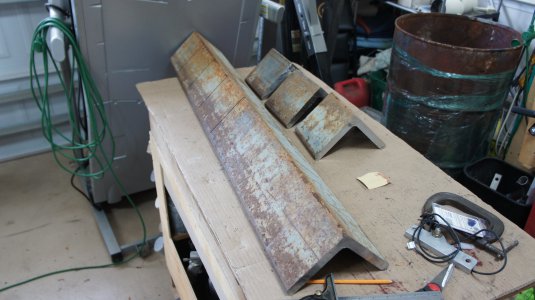
I've started work on the base already. I had to take my uncle the shop press that I built for him out of scrap steel. You can see it in the background, on the right edge of the video. It's a 2-hour drive, that I don't make lightly. So I had him cut the steel to length with his chop saw. We started by cutting a piece off the 20' length, and then chopped it to size. I have to do quite a bit of juggling to get this big steel in my 4x6 bandsaw, but check this out.


He cut it just slightly oversized. He has had that blade for 5 years, and it was getting near EOL, so this is what I ended up with:

dsc04907-jpg.364326

DSC04907.JPG
 
Last edited:
If there is anything that looks like it may cause you difficulty on the parts you are making, let me know ASAP so we can work it out.
Page 5: What is the R.750 cutout on the left side of the right drawing? I can't make out what it is used for.

Page 11: Is there any reason that the screws for the blocks can't be through holes?

Page 22: The walls for the worm side of the mount look mighty thick. Is this a part we would expect to clamp down on and then never move again, or would it be adjusted regularly? The worm side would be set-n-forget, I would expect, so the thick walls are just fine. How much force will need to be applied to move that 3/8" thick wall through such a short radius? Maybe I could make the part as is, and then mill material off of each of the angled sides till the forces are reasonable if necessary?
Page 5: That .750 cutout is clearance where the worm shaft goes thru.

Page 11: They could go thru. I made them blind so that swarf would not accumulate in them.

Page 22: The big hole will be clamp and forget. Once aligned it will never be used again. The small hole will only be used to engage the worm and never changed again unless you want to disengage the worm to use the rapid indexing. Not used during normal operations. I was going to make the walls thinner but wanted to keep the straight line to ease machining. I will look at that some more, or I could just let you go ahead and do some trials to get the right "feel", and then I can make the drawings match the part. (I have often had to make the drawing package match what the shop ended up actually making in the real world too)
 
Back
Top