Having problem milling 120 degree sections

It looks like the mating surface on the lead screw is machined part. Maybe make a templet from that, then transfer to your round stock before cutting.

Get a good straight on photo of it or if you can take it off and scan it and let @Ischgl99 do his magic!
 
I tried to scan a coupling I have to play with it in Fusion, but it is black and won't scan, so I painted it white to see if that would work better. Instead of watching the paint dry, I took a closer look at the coupling and I noticed the angles of the teeth were steeper than would be necessary to come to a point in the center, noticeably so, so I thought the same might be true for the OP's handle. I extended the angle lines of each tooth until they met, then drew a circle through all the points, and they all touch the center circle. So, it looks like instead of designing this with angles that would meet in the center that we have been assuming, they designed it for the included angle to be at a certain diameter from the center. If you take the average chord length of the tooth on the OD, and use the diameter of the center circle where the points meet and the OD, you should be able to come up with the angle that works. This assumes there is not much of a difference in the chord lengths of the teeth.


Capture2.PNG
 
@Ischgl99
May I ask you to do one more experiment?
Please extend all six angle lines to approximately (or a little past) the center of the central hole.
That will define a central (approximate) polygon.
Then add a central circle that best fits (most tangents) the polygon.
The radius of that circle is (approximately) the offset I spoke of.

The easy way to verify symmetry of the features in question is to ask @want2drive whether or not the handle(s) will mate (index) at any of the three 120° options. If the handle indexes at only one then the symmetry is ruled out. If the handle indexes properly at three rotational options, then symmetry will have been sufficiently proven to be the case.
 
Thank you all for the help here

Sorry for the delays but just got back from a short trip and tried my hand on CAD. I attached 2 photos, the one is just the raw data from the original piece. I attempted to do as Flyinfool suggested. I measured each segment ID and OD averaged those out and plotted on CAD. The CAD image is a screen pic. It is a 2005 version on a 2005 laptop. I am using the built in mouse so I have lots of issues to resolve there as well. I wont bore you with them here. Its a lousy pic is all I can say.

I wanted to give some feedback on this. Basically;

average OD width of the segments are .6867"
average ID is .4397".

ID = .755"
OD = 1.372"


FYI all CAD dimensions will be hard to see from the photo

When I plotted on CAD it determined the angle to 66 degree.
Extending the lines past the center point gave a dimension of .090" to the right +X and .078" to the left -X from center. I believe the difference is in my lack of being able to accurately place the lines and all the rounding/averaging from the raw data.

So everyone did a great job interpolating dimension from the photos.

So given this data I think I need to either set up each cut individually or if I understand the prior post set up, use the RT and offset my tool half diameter of end mill plus approx. .084" to compensated for the non radial faces. and adjust accordingly to bring it in to some reasonable tolerance. Something that looks like I knew what I was doing from 2-3' away.

Thank you for keeping up with this for me, hope I am not running you all in circles with it all.

And here I figured a 20-30 min job.
 

Attachments

  • raw data.jpg
    raw data.jpg
    129.8 KB · Views: 25
  • screen shot.jpg
    screen shot.jpg
    192.2 KB · Views: 23
Some times just copying the part is not the correct thing to do. Sometimes you have to figure out the designers intent and make your part to match that intent, even if all the dimensions are different, this might make you end up with a better part than the original. Manufacturing does not always make what the designer designed.
 
Sorry I did not answer the symmetry question extropic

Yes all the handles fit any location and any position on each one. Just for fun, I will need to follow up on the head on photo of the machine side of the coupler. I hope the data I provided will allow for the alternative of removing it from the machine for photos.
 
@want2drive

IMO, the measurement and CAD exercise you explained in reply #34 is not very useful.
Because of the corner radii, obvious on OEM part, your measurements would require more measurements and more complex geometry calculations to help us converge on the suitable angles and offset.

Instead, please report the measurement I requested in reply #27 and digest the rest of the information contained therein.
 
Thank you Flyinfool

The original parts are not snug fit with each other, they have play in the couplers. Just not as much as I do. The reason for all this is to clear a DRO head that I placed on the side for the machine for the Y axis. The original handle length hits it before the X axis runs it distance. At the time I figured, good small project to extend the handle to clear everything and the DRO scale and reader are tucked away and out of harms way. No problem.

Thank you
 
Thank you extropic

Please forgive my ignorance here and my inexperience.

I re-read your post and I can check that dimension for you. I hope its close to my CAD dimension.

Thank you
 
@Ischgl99
May I ask you to do one more experiment?
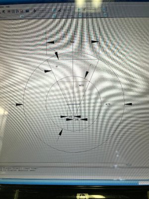
Please extent all six angle lines to approximately (or a little past) the center of the central hole.
That will define a central (approximate) polygon.
Then add a central circle that best fits (most tangents) the polygon.
The radius of that circle is (approximately) the offset I spoke of.

The easy way to verify symmetry of the features in question is to ask @want2drive whether or not the handle(s) will mate (index) at any of the three 120° options. If the handle indexes at only one then the symmetry is ruled out. If the handle indexes properly at three rotational options, then symmetry will have been sufficiently proven to be the case.
Is this what you are asking for? Note that I did not scale the drawing to the picture, so the dimensions there are just what size the sketch is and don't relate to anything in the real world.

Capture3.PNG
 
Back
Top