- Joined
- Jun 12, 2023
- Messages
- 41
Good morning
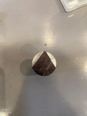
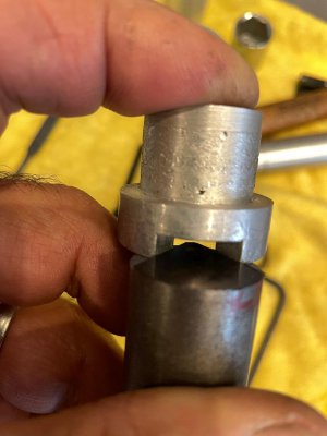
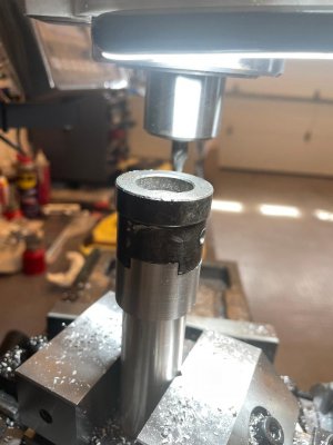
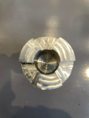
extropic: here is the 67 degree test Gage and the original handle coupler half as apposed to the machine couple half which I re installed on the machine. see pictures. The fit looks to match as predicted. I don't want to get ahead of anything here so advise on my next operation is appreciated.
Flyinfool, IschgI99: I'm sure that exercise is easy for you and is something I want to do as it seems to be knowledge I need. I am not that good on CAD at the moment, that last exercise took me 4hrs to produce because I forgot all the commands and need additional hardware to be better at it. The pin measurement I am still studying the the formula to see what "csc" stands for in the equation. I know "a" is the angle but it looks like the "csc" is some multiplier of it or designation of it so I need to do my research but it's not on any of the diagrams. In the mean time I only have a short time before heading south so I need to proceed with something I know if I am to complete this project before I leave. In my last job, I left all the calculating to the engineers and contractors. Now, I am wishing I did some myself. Lazy I guess, you never know what the future brings, never thought I would want to do this back then.
Thank you