Having problem milling 120 degree sections

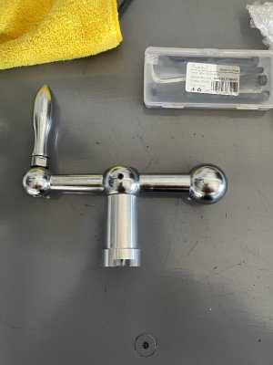
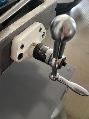
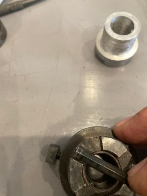
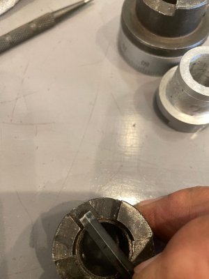
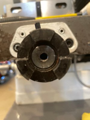
@want2drive How much play does the original handle have? I would think it would be better to match the part that is attached to the mill. Is that part machined, in the photo it looks as though it is.

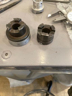
You said the handles fit in all directions and all locations. My guess is that the driven dog thing for the lack of proper terminology is machined, and the angles are 60°.

Now that being said. I'm just about as green as you, I only have a little over a year learning. And I have a lot to learn. What I think I would try is make a cardboard templet of the part that is on the mill. Blue up what the part I wanted to cut scribe some line on it and start cutting. I'm not saying that is the right way to do it, but that is what I would try.

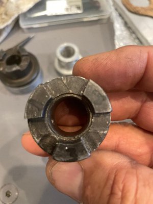
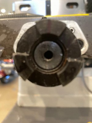
I've been playing with Fusion 360 like @Ischgl99 did with the handle. I can't say I'm doing it right but here is what I did the lines are evenly spaced at 60°. They don't line up just right, so, maybe the 60° is not right after all.

1692588174396.png
 
Last edited:
Good morning all

extropic; same thing basically, the only difference is I don't have .750" stock. I have 1.5" stock, instead of turning down to .750" I was going to cut the angle on one end and reduce the length/width to the size of the slot so the overall wedge is the same as you describe but on the end of a 1.5" round stock. Just didn't want to remove all that material of the piece I have left. Not that it matters I guess. Hope I explained that better for you. I do plan on extending the piece that is attached to the handle, not the one on the machine, in the picture of my prior post #47 the piece on that handle was my attempted version, it works just not matching well at the mating end. I also attached photo here. The right handle extension will be 3" the left handle extension will be 4.5".

Just for fun; Lots of info being conveyed, hopefully I can catch you up, "readers digest version". its been determined nothing on this OEM piece is cut to any standard dimension. going through several iterations of measuring, the piece is cut with some offset to the angles, it is believed to be .040". I am going to attempt to determine/verify the angles are cut at 67 degrees and verify the part on the machine is not different then the part attached to the handle. extropic is volunteering to put together a sequence to produce the new and improved version of my new extension.

Your thought on a template has been voiced by my brother in-law and is a valid way to re-produce the part IMO. I am pursuing this method because I want to learn how to accomplish these by laying out and machining from that. Just a knowledge/experience exercise that I think I need to acquire.

Thank you
 

Attachments

  • My extension.jpg
    My extension.jpg
    96.9 KB · Views: 8
  • original aluminum extension.jpg
    original aluminum extension.jpg
    97.6 KB · Views: 8
Good morning again

Some additional observations that were requested. I removed both hubs, left and right side, from the machine. The two hubs off the machine are cut the same. They are radially true except for the 1b 3a faces there is a gap in that plane going across them. Both pieces have the roughly same gap on the same 2 faces.

The 2 pieces from the handles are the same. They will not mate when put together. They only mate with the pieces that would be on the machine. The 2 pieces from the machine will mate together but have large gaps between the segments.

The offset as requested earlier from center on the pieces from the machine are;

used same method described in earlier post with Allen wrench
.015' on the one with the dial (right side)
.022' on the one without the dial (left side)

I am guessing either way is about the same, model off the pice from the machine or model off the handle piece. If I model off the machine piece do I lose interchangeability? And that is why they made the casting as they did.

Trying to get to old and wise.

Thank you
 

Attachments

  • both couplers.jpg
    both couplers.jpg
    117.6 KB · Views: 9
  • coupler segments identified.jpg
    coupler segments identified.jpg
    92.9 KB · Views: 9
  • Dial coupler gap.jpg
    Dial coupler gap.jpg
    81.4 KB · Views: 8
  • non dial coupler gap.jpg
    non dial coupler gap.jpg
    86.2 KB · Views: 7
  • hopefully better shot of machine coupler.jpg
    hopefully better shot of machine coupler.jpg
    79.8 KB · Views: 7
  • better shot 1.jpg
    better shot 1.jpg
    73.5 KB · Views: 8
One other note. I should say radially truer. I have no way to determine that precisely. Sorry
 
Sounds good on doing it the right way. By the way, I'm paying attention and learning how to do it right also.
 
The hubs look machined, so you should be able to measure them more accurately than the handles. Once you have measurements from that, you would make the opposite for the handle extension with some clearance to fit.

Something I’ve been wondering the past couple days, what is the point of these couplings? I can understand them on a knee, but these look like they are on the x and y axis. The handles on my mill are fixed and I have never seen the need to be able to rotate the position of them, or remove them. If they don’t serve any useful purpose, can you make just make an extension that fits on the leadscrew and avoid these couplings all together?
 
I often mill/turn test parts out of old 2x4s.
I have a wood shop and access to all sorts of wood. I make trial parts in hard maple sometimes. It machines very nicely. A router bit works best and turned at the highest speed you can. There are lots of woods that will serve the purpose, choose fine grained ones. And note that wood changes size with changes in moisture content. Seal it in a plastic bag when not in use. Chunks of plastic also work well. Some of them are also subject to absorbing moisture and changing size.
 
Thank you IschgI99

I have to say, I don't know what their purpose is other than being able to remove the handle and not disturb the thrust bearing that is behind them. I can tell you I don't think they were originally designed for this machine. After I cleaned them up I noticed they were originally for a tapered shaft there is a taper on the back side so, I think they took a part off the shelf and said this will work. Precision Matthews stated this on machine description: "Larger Knee Mill Style Table Handles, for Much Better Control By Hand" so maybe it was used to adapt the knee mill style handles to this machine.

I started to perform the pin measurements, only to find out that the largest drill shank I have is .500" and that almost goes through the bottom angle so I will need to invest in the proper tooling to perform that type of measurement. I will use extropic method for verifying the angles, I understand that process better than the others mentioned and though it wasn't difficult to remove the pieces from the machine, it is in pieces now and basically unusable. I need to reassemble it so I am able to properly use it to cut the angle gage and proceed. I have received many great ideas on verifying and measuring that I am running out of time to properly research them, complete this project and head back to Florida. I will follow up on them so I can have that knowledge going forward on other projects. I would like to have these pieces completed and back on the machine before I leave so I can winterize everything and get things packed up here.

I will keep posting with my progress and for any additional thoughts/comments until I run out of time and have to leave Maryland or they are completed and back on the machine.

Thank you
 
Instead of beating up your calculator you can use the 2 pin method of measuring the angles and enter all the dimensions into your cad program to to the math for you.

Since the handles fit in any orientation in any location, I am guessing that the design intent was for 60° angles. I also believe that the faces are intentionally offset from the center line. Now to decide just how far off center.

Wood works very well in both the metal cutting mill and lathe. It just gets sawdust everywhere. I use the shop vac instead of the coolant mister.
 
I started to perform the pin measurements, only to find out that the largest drill shank I have is .500" and that almost goes through the bottom angle so I will need to invest in the proper tooling to perform that type of measurement.
No need to buy new tooling, put a piece of metal in your lathe and turn one end to a diameter larger enough that it doesn’t pass through the small end of the angle, and turn the other end so that it fits at the top. You now have the pins for your measurements.
 
Back
Top