

-
Welcome back Guest! Did you know you can mentor other members here at H-M? If not, please check out our Relaunch of Hobby Machinist Mentoring Program!
You are using an out of date browser. It may not display this or other websites correctly.
You should upgrade or use an alternative browser.
You should upgrade or use an alternative browser.
Info needed for installing/setting up pm940m
- Thread starter tim81
- Start date

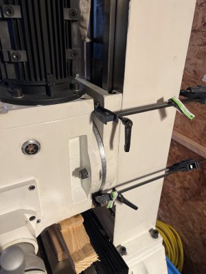
You really only need a board under the head just behind the spindle to adjust the gib. There is a flat spot there. I would not put the board under the spindle itself. Why stress it? When my mill was shipped to me it had a board located between the table and the area just behind the spindle.. The put the board there and then lowered the head until the weight was on the board. The board was a piece of scrap thick plywood cut to about 1.5 x 2 x 8" or so. Just lower the head until it is resting on the board and the board does not fall out. Do not force it down so that the lead screw is binding.
On the other hand if you are going to pull the gib all the way out you will need more than just one board. When I want to do this I use a long steel wood working clamp and clamp the saddle way to the column so that the saddle/head cannot fall off the column. (I don't think that the ways would clear each other if the gib was completely removed but why risk it and why let them get beat up? ) I would not even take the chance. Anyway, when you clamp the column to the saddle some of the paint may come off. Mind did. The cast iron under the paint has a thick layer of soft bondo compound (like automobile body bondo to fill holes) on it to make it look smooth. The casting is very rough. A very ugy finish. So when you clamp to it it tends to crush and the paint breaks away with the bondo.
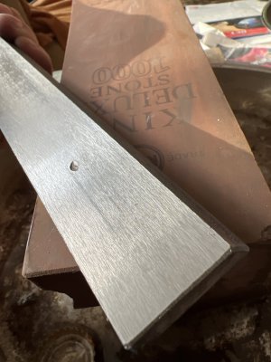
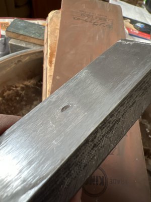
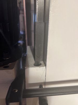
Gib photos. In the photos it looks like the screw head has a pretty good over lap with the edges of the gib. You should be safe at the screw. It may just be the high mag of the pictures, but maybe you should clean the surfaces of the column half of the ways. They look a bit dirty. Just rub them down with a way oiled rag or paper towel.
On the other hand if you are going to pull the gib all the way out you will need more than just one board. When I want to do this I use a long steel wood working clamp and clamp the saddle way to the column so that the saddle/head cannot fall off the column. (I don't think that the ways would clear each other if the gib was completely removed but why risk it and why let them get beat up? ) I would not even take the chance. Anyway, when you clamp the column to the saddle some of the paint may come off. Mind did. The cast iron under the paint has a thick layer of soft bondo compound (like automobile body bondo to fill holes) on it to make it look smooth. The casting is very rough. A very ugy finish. So when you clamp to it it tends to crush and the paint breaks away with the bondo.
Gib photos. In the photos it looks like the screw head has a pretty good over lap with the edges of the gib. You should be safe at the screw. It may just be the high mag of the pictures, but maybe you should clean the surfaces of the column half of the ways. They look a bit dirty. Just rub them down with a way oiled rag or paper towel.
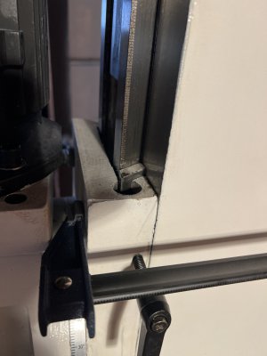
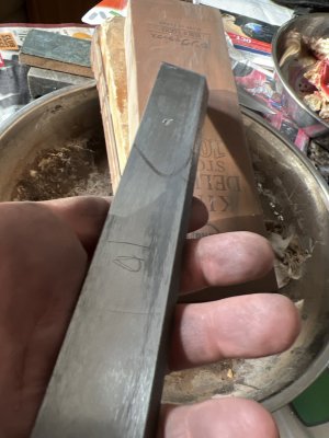
I was writing as you posted your pictures of the gib. Great shots. I see the dig mark from the lock screw tip. Your gibs look a lot nicer than mine did when I took them out. clean them up and put them on your table and you can check the flatness in both directions. If it is high in the center it will spin on one point. I suggest you also take some measurements of the gib while you have it out. For the future reference. Length, thickness at several points along the length, Width, (corner to corner) along the width. I did this every inch and put it in a spread sheet to see if it varied. Some day I will make new gibs. By doing these measurements and if you find them to be straight line plots (thickness vs length etc) as they should be.... it will be useful. In theory if you know the tapper angle of the thickness along the length and the width at one point you can figure most of every thing else out.
My understanding is that they make a gib to fit, but make it extra long. They then slide it in and to finalize the fit of the gib and they cut it off when it is tight in the saddle.
Take some pictures of the scrapping. After you put it back and run it up and down a bunch you can take it out again and look at the scrapping pattern again. If it has worn off in some spots you will know where it is rubbing the most etc. Or you can just blue the scrapping marks and put it in and run the saddle up and down a couple of times and then look at the blueing. If you don't smear it off.
Thanks a lot man will slide it out and use the tools I bought to measure it. Almost poeticI was writing as you posted your pictures of the gib. Great shots. I see the dig mark from the lock screw tip. Your gibs look a lot nicer than mine did when I took them out. clean them up and put them on your table and you can check the flatness in both directions. If it is high in the center it will spin on one point. I suggest you also take some measurements of the gib while you have it out. For the future reference. Length, thickness at several points along the length, Width, (corner to corner) along the width. I did this every inch and put it in a spread sheet to see if it varied. Some day I will make new gibs. By doing these measurements and if you find them to be straight line plots (thickness vs length etc) as they should be.... it will be useful. In theory if you know the tapper angle of the thickness along the length and the width at one point you can figure most of every thing else out.
My understanding is that they make a gib to fit, but make it extra long. They then slide it in and to finalize the fit of the gib and they cut it off when it is tight in the saddle.
Take some pictures of the scrapping. After you put it back and run it up and down a bunch you can take it out again and look at the scrapping pattern again. If it has worn off in some spots you will know where it is rubbing the most etc. Or you can just blue the scrapping marks and put it in and run the saddle up and down a couple of times and then look at the blueing. If you don't smear it off.
")
I looked back at your gib pictures. I see no scraping marks. I was just ground and then installed. This looks nice, but... Scraping marks are patterns of high and low spots and also provide a place for the oil to sit (a local source of oil) between the two rubbing metal parts. As long as the mating way surfaces say oiled that is what is important. If you want there is a lot on the form about scraping. If you want o see a wear pattern, then just make a bunch of shallow regular scratch marks across the gib face, that is in contact with the column way, at regular intervals before you put it back.