[Newbie] Jet 1236py reversing switch

F7F8AC3A-65EC-48B6-AADA-8C80E6F9D5EE.jpeg517D8A88-CAD8-41D9-AD1F-DF0F3ADD932D.jpeg
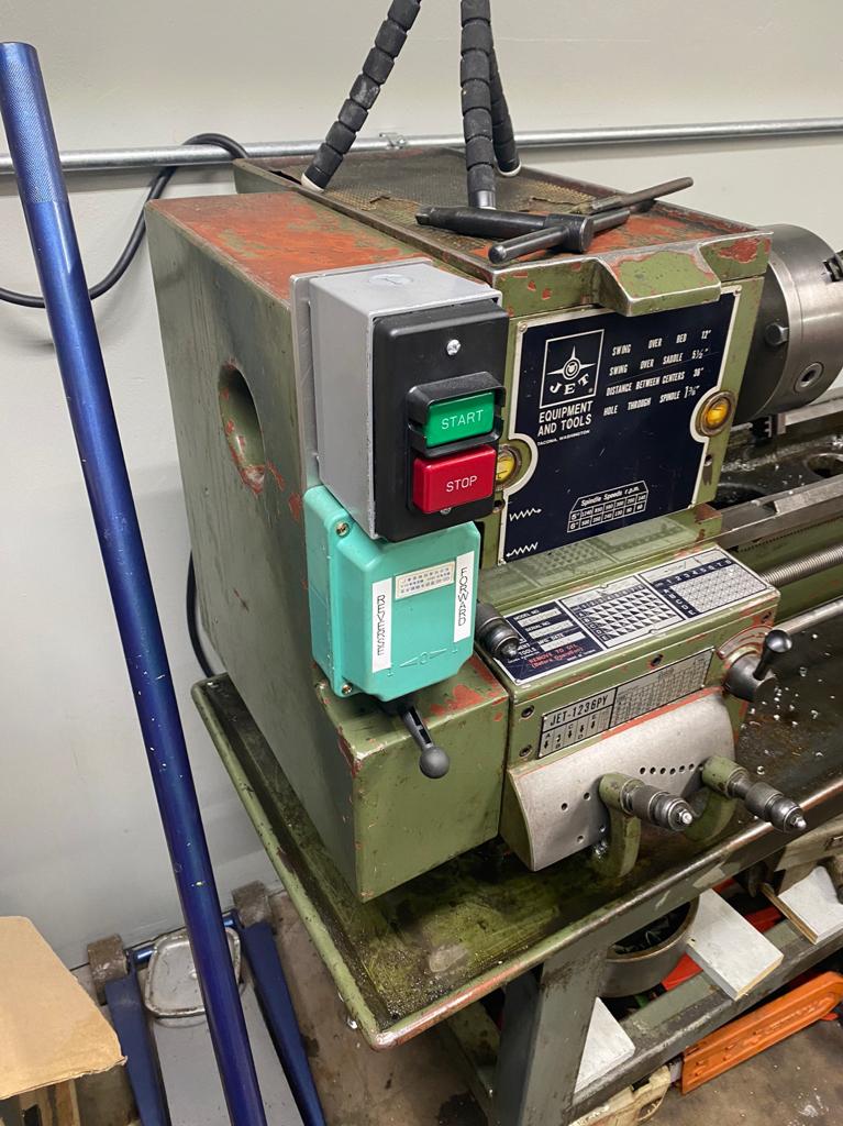
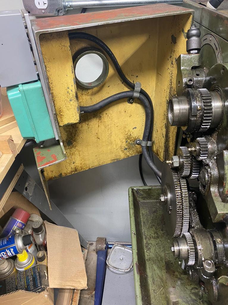
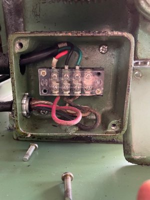
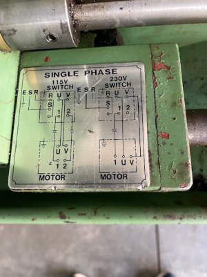
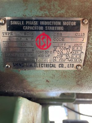
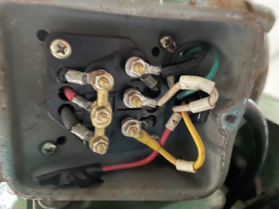
So last night I gathered enough courage to try and wire up my switch. IT WORKS!!!! Believe me I’m over here smiling ear to ear. Thank you all so much. I used the diagram in post #23. I runs backwards from what I’d like so I’m guessing I need to switch the run legs? The pictures are of the motor connections and the old switch. I probably will be installing a stop switch with a large stop paddle. Did jet ever put a foot brake on these type of machines? If so could someone post some pictures of the braking system. I might try to make something up for a foot brake. Again thank you very much to all of you
 
Always a 50/50 chance the switch handle will be backwards from desired. No problem. Move the black wire (5) at the drum switch down to the N.C. terminal. (post #23)
Glad it got you going again! Good idea about adding a stop switch with a big red button. I think the larger Jet lathes had foot brakes but not the smaller 10" models- I think you can get by without one, just work safely and don't leave the chuck key in the chuck when you fire it up
-Mark
ps be sure your lathe is well grounded for safety
 
Last edited:
I wanted to follow up with a few pictures of how this turned out. Thank you to everyone for all the help.

03250c9d5419a16a9cae281519122a66.jpg

ddb7188ad7e4f875a793acc0f8c8df32.jpg


Sent from my iPhone using Tapatalk
 
Hello - I'm another newbie who just picked up a 1985 vintage Jet 1236PY lathe at an estate sale (can't ask the last owner any questions). I have tried to absorb all the prior wiring discussions but paraphrasing the line Clint had in one of his movies "a man has got to know his limitations". I'm having a little trouble relating the wiring diagrams to the physical hardware. For instance, the connection box under the motor seems to have a few extra wires with different color insulation than the diagram. The manual also has two wiring diagrams showing "the switch" and "the motor" which has me confused.
There is a data plate on the lower rear belt cover that says the motor is wired for 120V. My wiring currently does appear different than what was previously posted by Walz10; not surprising as his is wired for 220V . The data plate on my (original) motor says the lathe can be wired either 120V or 220V single phase. I'll will have to do some wiring in the garage to either add a higher amp 120V circuit or a 220V circuit for this lathe. Question: Should I change over to 220V? The odd thing about my lathe is that there is no "on/off" switch of any kind. Perhaps the last owner used the wall plug or the circuit breaker to turn it off or on, which hardly seems ideal in an emergency. I am thinking at a minimum I should add an "on/off" switch.
This lathe does have the "SW-900" switch to the right of the quick change gearbox which I believe changes the direction of the carriage/cross feed. This switch is controlled by a long square rod which is below and parallel to the carriage lead screw and feed rod that run along the length of the lathe bed. There is a lever mounted on the right side of the carriage that rotates the square rod, (where upon I can hear "clicks" in the switch). Question: Does this switch just reverse the spindle so I don't need a separate reverse switch like Walz10 added?
Per the rules of this forum I can't post any photos or attachments yet until I post a few more messages. I really appreciate any suggestions or input, THANKS in advance.
 
Hi, if the motor is 1 HP or more it's best to run on 220v
The apron lever you mentioned is/was for reversing the motor, in conjuction with a contactor/control box which
may have been removed. The apron switches usually don't have the current rating to control the motor directly.

You might consider installing a stand-alone switch for forward/off/reverse and give up the apron lever feature for now.
If in the future you install a 3-phase motor/ VFD (variable frequency drive) you could recover the apron switch functions

This type of switch is low cost/ easy to install:
 
Last edited:
markba633csi - Thanks for the fast response. It has a 1HP motor so I will go the 220V route per your recommendation. There is a junction box(?) under the left end of the head stock which is where the power cord comes in. The wires going out of this junction box then go over to the switch next to the quick change gearbox. The wires going out of the switch go to over to the box on the underside of the motor, same as pictured in post #31. I will take some pictures tomorrow and try to post, along with the wiring diagrams that came with my manual.
Thanks again.
 
Here is a photo of the "junction box" under the left side of head stock. Is this the contacter/control box you referred to? The lower wire is the power cord to the wall plug, the upper wires go over to the apron switch.
 

Attachments

  • IMG_3236.jpg
    IMG_3236.jpg
    66 KB · Views: 1
Looks like I am allowed to post photos now.. This photo is of the apron switch which is mounted next to the quick change gearbox. I am confused about the wiring diagram... is the "switch" portion for the connections inside this (switch) box and the "motor" are actually the connections in the box under the actual motor per post (as shown in #31)?
 

Attachments

  • IMG_3235.jpg
    IMG_3235.jpg
    71 KB · Views: 5
Here is a photo of the data plate on the motor itself.
 

Attachments

  • IMG_3240a.jpg
    IMG_3240a.jpg
    76.9 KB · Views: 1
Here is a picture of the box under the motor, similar to what was posted in #31, except mine is currently wired 120V (I think!). Not really obvious in the photo, but the terminals on the left are labelled "2", "6", "3", top to bottom on the left and "W", "V", "U" top to bottom on the right, molded in the plastic. This seems to match the "motor" portion of the manual wiring diagrams. There are two wires going to terminals "W" and "U", I need to double check in also to "V".
 

Attachments

  • IMG_3243.jpg
    IMG_3243.jpg
    105.7 KB · Views: 4
Back
Top