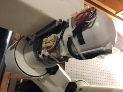
Mike's 6-Axis Articulated Robot

Still working on the encoder interface code, but running into a couple issues. I'll post an update soon.

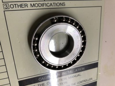
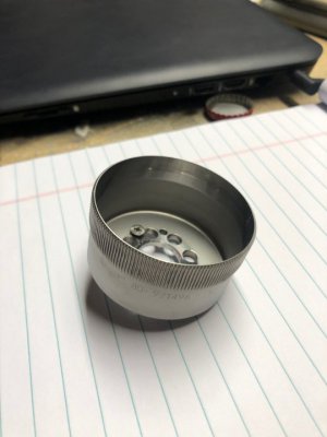
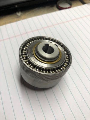
I completed cleaning of Joint 3 gearbox. The wave generator from the harmonic drive was also starved of lubrication like joint 2, and was covered in mud brown deposits, however it was much less gritty.

image142.jpg

I fully disassembled the wave generator and cleaned it with WD-40, alcohol, and dish soap. It took some work to remove the dried grease and grit from the nooks and crannies.

image143.jpg

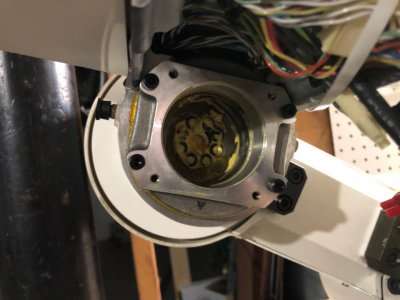
With this gearbox, the harmonic drive flex spline had two tapped holes which allowed me to use them to push the cup out.

image144.jpg

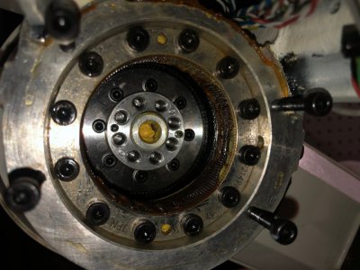
Once removed, I could clean the ring gear which you can see in the picture below. This can be removed, but there was no reason to do so as it can be cleaned in place with a tooth brush.

image145.jpg

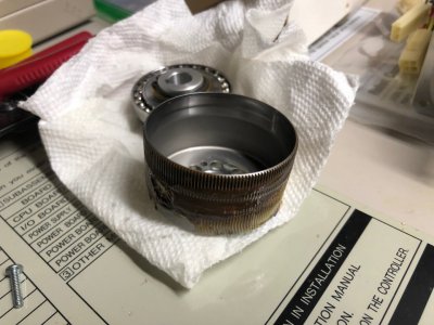
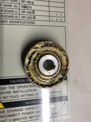
Below you can see the flex spline cup. Imagine machining this. It has extremely thin walls with precision spline teeth around the perimeter. The steel is also a special alloy with good fatigue resistance as this part flexes many billions of times during its lifespan. This component is the output of the gearbox. The teeth were fairly dirty and I was glad to have the opportunity to clean it. Wish I could have pulled the J2 cup, but there were no extraction holes.

image146.jpg

All cleaned up

image149.jpg

And assembled with the clean wave generator. Rotating the input shaft creates a travelling wave along the perimeter of the spline teeth.

image150.jpg

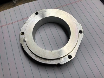
I screwed up removing the motor mount thinking the motor mount holes were tapped through (hoping to use these to push the motor mounting plate off - it was stuck on with sealant). When I bottomed out the screws, it dented the rear surfaces outward. Whoops! I used a punch and hammer to peen the metal back to the original form, then cleaned it up with a fine stone. I hate messing stuff up, but I repaired this quite well. Picture is before the repair.

image153.jpg

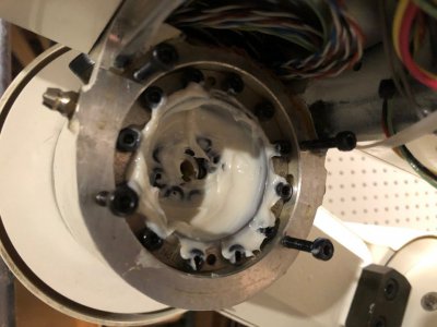
The gearbox was prepacked with the new low viscosity lithium grease.

image152.jpg

And the motor was mounted again. A couple dozen pumps of grease through the nipple fully flushed the system. Gearbox sounds great and is very quiet.

image156.jpg

Will keep going through each gearbox.

-Mike
 
Back to some of the encoder interface board stuff.

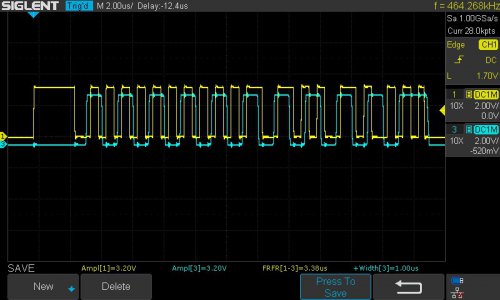
I was able to get the microprocessor to line up its sampling of a periodic timer within the permissible 250ns. In fact, the sync is much more accurate than that, usually within 2-3ns. Measurement #3 is the sync value, target is 3.375us and the average is 3.38us, potentially within rounding error.

The yellow is the input signal, and the blue signal represents each moment the yellow signal is sampled (represented by the transitioning edge of the blue signal. The rising or falling edge of the blue signal needs to be perfectly synced in the brief period before the yellow signal transitions to get a good reading. The blue signal identifies the start bit and syncs, then takes 21 samples, wait for the stop bit to pass, and re-arm the trigger.

image130.jpg

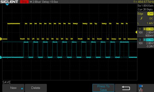
This works great, however turning on "Fast Capture" on the scope and display persistence, I could see the blue signal would occasionally glitch and trigger at the wrong time. This is no good.

image128.jpg

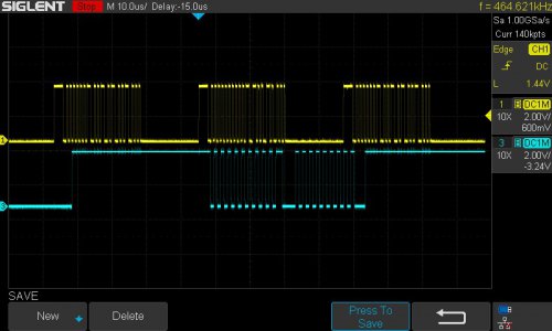
Took me a long time to actually capture a glitch. Seems like a 1 in 10000 occurrence, but using the scope's segmented memory and search functions, I was finally able to get a capture. It seems like in some rare cases, the periodic timer ends up waiting for a very long time, much longer than the prescribed delay. when this happens, the whole sequence gets off and takes several serial packet cycles before the signal can re-sync.

image132.jpg

I tried many things to get rid of these glitches but nothing seemed to work. This could be dealt with by verifying the CRC and throwing away these rare bad packets, but I would prefer a more stable solution.

I'm now a member on the Teensy microprocessor forum and there are many people much smarter than me there. They recommended the best way to approach this is to use the hardware clock cycle counter capture option. Basically this is a fully hardware implemented circuit that captures the exact clock count when an input changes from low to high or high to low. By comparing the difference between two samples, you can know the pulse width that was captured. This is done in hardware and really offloads the effort from the processor. I got a simple program working which prints out the width of each captured pulse, but does not trigger on the start bit.

C++:
#include "Arduino.h"

constexpr unsigned maxEdges = 14;
uint32_t  cap_index;
volatile uint16_t cap_vals[maxEdges];

IMXRT_TMR_CH_t& ch = IMXRT_TMR1.CH[2]; // TMR1_2 -> input pin 11

bool recording = false;

void onCapture()
{
    ch.SCTRL &= ~(TMR_SCTRL_IEF); // no need to check which flag was set since we only enabled IEF
    if (recording)
    {
        cap_vals[cap_index++] = ch.CAPT;  // store the captured value
        if (cap_index >= maxEdges)
        {
            recording = false;
            cap_index = 0;
        }
    }
    asm volatile("dsb"); // wait for clear  memory barrier
}

void initTimer()
{
    cap_vals[0] = 0;
    cap_index   = 0;

    *(portConfigRegister(11)) = 1;        // Alt1, use pin11 as input to TMR1_2
                                          //
    ch.CTRL  = 0;                         // stop timer
    ch.SCTRL = TMR_SCTRL_CAPTURE_MODE(3); // capture at rising and falling edges
    ch.SCTRL |= TMR_SCTRL_IEFIE;          // enable input edge flag interrupt
    ch.LOAD = 0;

    attachInterruptVector(IRQ_QTIMER1, onCapture);
    NVIC_ENABLE_IRQ(IRQ_QTIMER1);

    ch.CTRL = TMR_CTRL_CM(1) | TMR_CTRL_PCS(8 + 0) | TMR_CTRL_SCS(2); // source: peripheral clock, prescaler 0, use counter 2 input pin for capture
}

void setup()
{   
    initTimer();
    recording = true;
}

void loop()
{
    if (!recording)
    {
        for (unsigned i = 0; i < maxEdges - 1; i++)
        {
            uint16_t x;
            if (cap_vals[i + 1] > cap_vals[i])
            {
                x = (cap_vals[i + 1] - cap_vals[i]);
            }
            else
            {
                x = (uint16_t)0xFFFF - (cap_vals[i] - cap_vals[i + 1]);
            }
            Serial.printf("%.2f ", 1E6 * x / F_BUS_ACTUAL);
        }
        Serial.println();
    }
    recording = true;
}

I've been trying to get the program to not start a capture until a start bit is found, thus anchoring the printed data with a start bit first and one serial packet per line. Unfortunately, right now, I don't have that working.

Will keep updates coming,

Mike
 
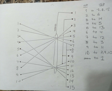
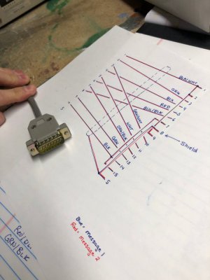
Had another eBay seller of a NOS teach pendant with cable message me yesterday with the ohmed out cable! Some people are just awesome.

image158.png

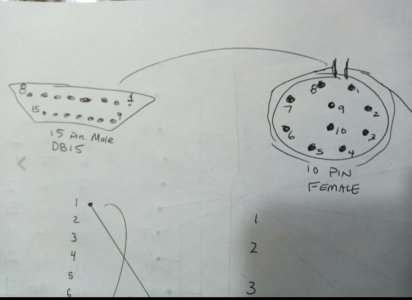
At first I was worried because none of the connections lined up. Then I realized from his other sketch that he got the DB15 pin order wrong. Once I transposed the pin numbers, things starting looking great!

image159.png

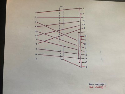
Referencing both messages, I overlaid the wiring diagram and got a 1:1 match! This is awesome. I'm going to go ahead and make that cable next.

image160.jpg

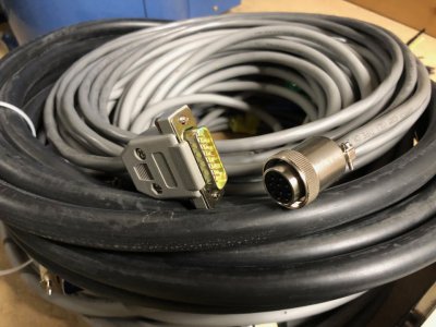
I was only able to find the 6m "extended" encoder feedback cable, and I opted to match that length when I bought the robot power cable. That could mean the robot could be located as much as 20' from the control box. I think I will match that length with the teach pendant cable as well, so you can always reach the robot with the teach pendant. The manual lists a 6m option for the teach pendant cable so I think this should be OK.
 
Started making some cables.

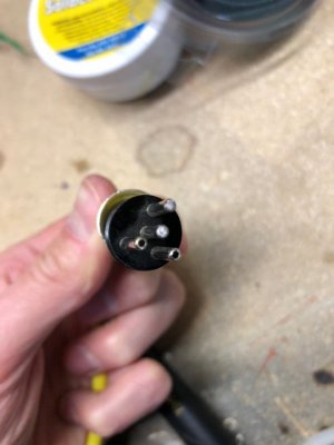
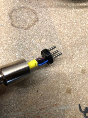
A warm up was the ESTOP cable. This one used the mystery connector. It was a bit funny because it solders from the front (there is no metal inside the connector to solder to. This was actually kinda tricky to not get solder all over the outside of the contact pin.

image161.jpg

image163.jpg

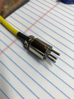
And all done! I used some 4 conductor sensor cable (6m long) which has a bright yellow jacket that makes me think of safety :D. I have an ESTOP box which I can put on the other end. Two conductors are soldered to pins and the other two are jumpered. This allows me to use two ESTOP contacts if I'd like for better safety.

image164.jpg
 
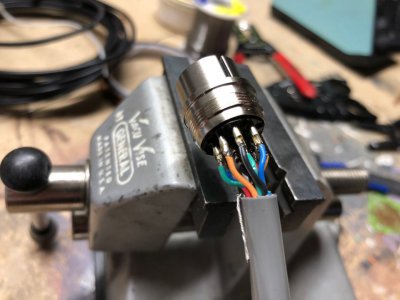
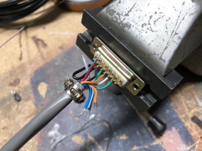
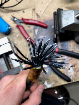
Next was the round connector for the teach pendant. The connector body is very short, so the exposed wires at the end of the jacket also needed to be very short. This made it quite difficult to get the soldering iron in there to work on it. Picture makes it looks easier than it was. I used some L-Com D-Sub 15 conductor cable with a foil shield and drain wire. I only needed 10 conductors so 5 were clipped. Like the rest of the cables, I chose to make this 6m long as well.

image165.jpg

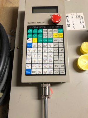
And this end plugged into the Teach Pendant.

image169.jpg

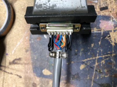
The other end terminates in a DB-15 standard density connector. I chose to make the jumper connections on this end of the cable.

image170.jpg

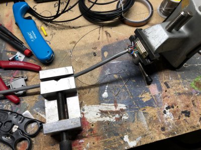
Some extra vises really helped with holding the cable since you need at least 3 hands to solder.

image171.jpg

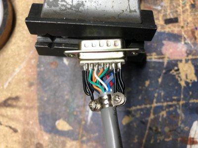
These photos show the black wire jumpers. These got tucked inside the plastic shell.

image172.jpg

image173.jpg

Worked against my cable drawing.

image174.jpg

All done!

image177.jpg
 
Last edited:
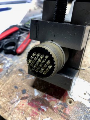
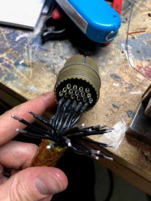
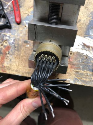
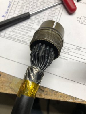
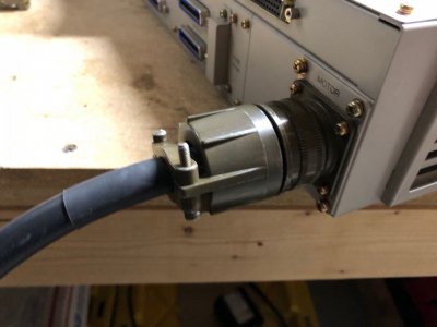
Next I started on the motor power cable. This connector (MIL-DTL-1566) was much larger and quite a bit easier to solder than the last connectors, but the cable was also very stiff and hard to work with.

image178.jpg

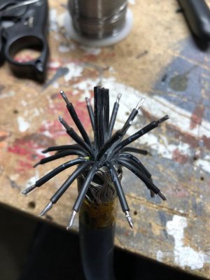
I got the ends of each conductor tinned and cut to length.

image179.jpg

I also applied a small glob of rosin flux to each pin.

image180.jpg

Since the wires could be stripped longer, I was able to add a small bit of heat shrink to each conductor. This keeps it tidy and prevents shorts, although I doubt it has 600V dielectric strength to insulate the drive PWM output.

image181.jpg

I got one more row past this done before calling it a night. It is tedious but also quite enjoyable. I have to do the exact same thing on the other end of the cable.

image182.jpg
 
This is a really great thread and I am glad you are doing it in detail like this.

I think at this point it is getting close to the scene in Iron Man 1 (Or maybe 2) where Tony Stark puts sensors on his own arm and that makes the robotic arm move like his own...
 
Made some more progress on the cables. Motor power cable is done. The controller end was soldered much like the robot end.

image183.jpg

All done! My careful selection of wire numbers to pins left the cable uncrossed at either end. This is important because there wasn't enough room to deal with crossed wires.

image184.jpg

Some heat shrink completed the connection.

image186.jpg

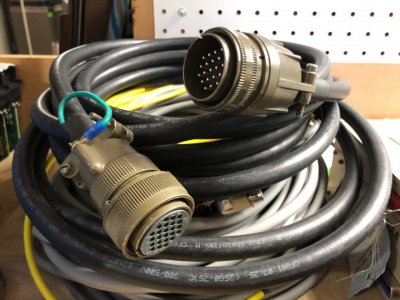
Beauty shot, stacked on top of the cables. All I have left now is the power cable, a grounding conductor between the control and the robot body, and the valve/end-of-arm-tooling (EoAT) connector. I justed ordered those connectors from eBay and Digikey. Not too expensive thankfully!

image189.jpg

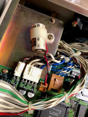
I chatted with the tech support guy from Denso again and he gave me some great news. Apparently the only data that is battery backed in the controller is the user programs and calibration parameters. All critical parameters related to the robot geometry and the actual control functions of the box are saved in EEPROM. This means that I don't need the parameters set or the floppy reader to get this working! He shared a simple procedure to wipe corrupted parameters and programs from the control once I boot it up. From there I should be able to run the calibration sequence, enter the RANG calibration parameters from a label on the robot, and get it running!

The control will need a new 3V battery. I bought one from Digikey for $5. I'll need to solder the wires and connector to it myself. This is a non-rechargeable battery.

image192.jpg

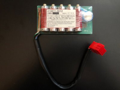
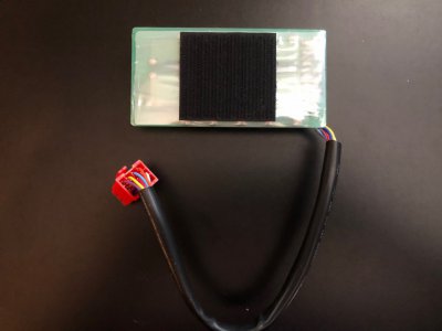
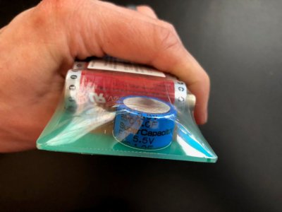
I also need to replace this board. Denso does not make them anymore so I plan to either re-populate or build a custom PCB to do the same thing as this one is. The batteries were bought from Digikey for $8 each and a new 5.5V super capacitor for $4.

It would be helpful to have spare boards and connectors for both batteries to facilitate the swap 2 years from now.

image203.jpg

image204.jpg

image205.jpg

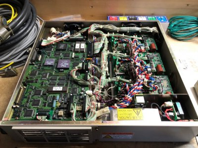
And here is a beauty shot of the entire control box again!

image202.jpg

I need to pick up some wire to build the power cable and I need to get some electric service installed in my basement. A friend of mine has offered up a 240V input 208V output 2kVA transformer which will get this box powered.

I still need to ohm out all the cables to verify they are correct. Additionally, I want to do some sleuthing inside the control box to verify the motor power cable is straight-thru. I only have a pinout for the robot end of the cable. I expect it to be, but cannot be certain.
 
I've been working on the coding of the feedback interface boards. As a reminder, these are NOT needed to run the robot with the original control, but they will be necessary if the robot is to be run by a Rockwell Automation servo drive.

I'll spare the nitty gritty details here since they are probably boring, but here is a link to another forum where I got a lot of help on the code: https://forum.pjrc.com/threads/54962-Interrupt-on-Rising-and-Falling-on-the-same-pin

The current implementation of the code (not written by me!) uses a hardware based clock cycle capture function to measure pulse width of the bit stream, pass that to a circular buffer using Direct Memory Addressing (DMA), and is decoded and printed to the serial port. The hardware capture and DMA make sure that all timing critical functions are handled in hardware and are free of processor latency. The decoding is done more slowly when the processor has time to service the requests.

My original code and the hardware cycle counter capture method without DMA both failed occasionally when some high priority processor interrupt took over and blocked reading the edges. The CRC still needs to be implemented, and this would help resolve that issue, but the DMA route does not seem to suffer from this issue.

I still need to read the quadrature signals from the encoder to increase the single turn resolution from 11 bits to 13 bits, borrow an Allen Bradley TLY motor with Tamagawa feedback from work and characterize its communication, then finally program the microcontroller to generate response packets to the drive that emulate the TLY motor. Lots of work to go, but having this part working is a big step forward.

Here is the code (Reminder, this is a Teensy 4.1 running Teensyduino firmware, so the implementation on another microcontroller will be different, especially the hardware and DMA calls):

Main function:
C++:
#include "Arduino.h"
#include "decoder.h"

Manchester::Decoder decoder;
Manchester::TS5643Field old, result;

void setup()
{
    decoder.begin(2E6); // 500ns clock
}

void loop()
{
    while (!decoder.resultBuffer.isEmpty())
    {
        decoder.resultBuffer.pop(result);
        Serial.println(result);
        /*if (result.count != old.count + 1)
        {
            Serial.printf("Error %d, %d --------------------------------\n", old.count, result.count);
        }*/
        old = result;
    }
    delay(1); // do something else, make sure you don't spend too much time otherwise the edge buffer might overflow and you'll loose data
}

void yield()
{
    decoder.tick(); // tick the decoder from yield to get ticks even during delays and other time consuming tasks...
}

A non-interrupt blocking circular buffer implementation:
C++:
#pragma once

#include <Arduino.h>

template <typename ET, size_t S>
class RingBuf
{
public:
    /* Constructor. Init mReadIndex to 0 and mSize to 0 */
    RingBuf();

    /* Push a data at the end of the buffer */
    bool push(const ET inElement);

    /* Pop the data at the beginning of the buffer */
    bool pop(ET& outElement);

    /* Return true if the buffer is full */
    bool isFull() const { return mSize == S; }

    /* Return true if the buffer is empty */
    bool isEmpty() const { return mSize == 0; }

    /* Reset the buffer  to an empty state */
    void clear() { mSize = 0; }

    /* return the size of the buffer */
    size_t size() const { return mSize; }

    /* return the maximum size of the buffer */
    size_t maxSize() const { return S; }

private:
    ET mBuffer[S];
    size_t mReadIndex;
    size_t mSize;

    size_t writeIndex();
};

template <typename ET, size_t S>
size_t RingBuf<ET, S>::writeIndex()
{
    size_t wi = mReadIndex + mSize;
    if (wi >= S) wi -= S;
    return wi;
}

template <typename ET, size_t S>
RingBuf<ET, S>::RingBuf()
    : mReadIndex(0), mSize(0)
{
}

template <typename ET, size_t S>
bool RingBuf<ET, S>::push(const ET inElement)
{
    if (isFull()) return false;
    mBuffer[writeIndex()] = inElement;
    mSize++;
    return true;
}

template <typename ET, size_t S>
bool RingBuf<ET, S>::pop(ET& outElement)
{
    if (isEmpty()) return false;
    outElement = mBuffer[mReadIndex];
    mReadIndex++;
    mSize--;
    if (mReadIndex == S) mReadIndex = 0;
    return true;
}

Header for the DMA edge capture:
C++:
#pragma once

#include "DMAChannel.h"

namespace Manchester
{
    class EdgeProviderDMA
    {
     public:
        static void init();

        static uint16_t popTimestamp();
        static bool hasElements();

     protected:
        static uint8_t tail;
        static DMAChannel dmaChannel;
        static constexpr IMXRT_TMR_CH_t* ch = &IMXRT_TMR1.CH[2]; // TMR1 channel 2 -> input pin 11,
    };
}

Code for the DMA edge capture:
C++:
#include "edgeproviderDMA.h"
#include "pins_Arduino.h"
#include <cstdlib>

namespace Manchester
{
    constexpr size_t bufSize = 256;                                         // DMA buffer for edge timestamps (512 bytes, 256 timestamps)
    uint16_t buf[bufSize] __attribute__((aligned(512)));                    // The DMA controller will replace the lowest n-bits of the address by a counter
                                                                            // to implement the circular buffer -> we need to align the start address of the buffer
    void EdgeProviderDMA::init()                                            // such that it corresponds to a countervalue of 0
    {                                                                       //
        *(portConfigRegister(11)) = 1;                                      // ALT1, use pin 11 as input to TMR1_2
                                                                            //
        ch->CTRL  = 0;                                                      // stop timer
        ch->SCTRL = TMR_SCTRL_CAPTURE_MODE(3);                              // both edges, enable edge interrupt
        ch->LOAD  = 0;                                                      // reload the counter with 0 at rollover (doesn't work without setting this explicitely)
        ch->DMA   = TMR_DMA_IEFDE;                                          // DMA on capture events
        ch->CTRL  = TMR_CTRL_CM(1) | TMR_CTRL_PCS(8 + 3) | TMR_CTRL_SCS(2); // start, source: peripheral clock, prescaler 3 (=> dt = 1/150Mhz * 8 = 53ns resolution, 2^15 * 53ns = 3.5ms max), use counter 2 input pin for capture
                                                                            //
        dmaChannel.begin();                                                 //
        dmaChannel.triggerAtHardwareEvent(DMAMUX_SOURCE_QTIMER1_READ2);     // trigger DMA by capture event on channel 2
        dmaChannel.source(ch->CAPT);                                        // DMA source = capture register (16 bit)
        dmaChannel.destinationCircular(buf, bufSize * sizeof(uint16_t));    // use a circular buffer as destination. Buffer size in bytes
        dmaChannel.enable();
    }

    uint16_t EdgeProviderDMA::popTimestamp()
    {
        return buf[tail++];
    }

    bool EdgeProviderDMA::hasElements()
    {
        return dmaChannel.destinationAddress() != (buf + tail);
    }

    DMAChannel EdgeProviderDMA::dmaChannel;
    uint8_t EdgeProviderDMA::tail = 0;

}

Header file for the bit stream decoder:
C++:
#pragma once
#include "RingBuf.h"
#include "TS5643Field.h"

namespace Manchester
{
    union frame_t
    {
        struct
        {
            uint32_t modemAddress : 2;
            uint32_t payload : 15;
            uint32_t frameAddress : 1;
            uint32_t frameCRC : 3;
        } bits;
        uint32_t data;
    };

    using ResultBuffer = RingBuf<TS5643Field, 10000>; // Keep results

    class Decoder
    {
     public:
        void begin(float baudrate);
        void tick();
        ResultBuffer resultBuffer;

     protected:
        bool decode(uint16_t dt, uint32_t* f0, uint32_t* f1);
        bool initialized = false;

        uint32_t bitCnt;
        frame_t frame0, frame1;
        frame_t* currentFrame;
        TS5643Field received;
        bool edge;

        enum states {
            SYNCING,
            SYNCED,
        } state = states::SYNCING;
    };
}

Code for the Bitstream Decoder:
C++:
#include "decoder.h"
#include "edgeproviderDMA.h"

namespace Manchester
{
    void Decoder::begin(float baudrate)
    {
        resultBuffer.clear();
        EdgeProviderDMA::init();
        state        = states::SYNCING;
        currentFrame = &frame0;
        initialized  = true;
    }

    void Decoder::tick()
    {
        if (!initialized) return;

        //static uint32_t oldCount     = 0;
        static uint16_t oldTimestamp = 0;

        while (EdgeProviderDMA::hasElements())
        {
            uint32_t payload_0, payload_1;
            uint16_t timestamp = EdgeProviderDMA::popTimestamp();
            uint16_t dt        = timestamp - oldTimestamp;
            oldTimestamp       = timestamp;

            if (decode(dt, &payload_0, &payload_1)) // If decoder returns true, the payloads of the first and second frame are valid
            {
                TS5643Field field;
                field.count = (payload_0 & 0x7FFF) | ((payload_1 & 0x1FF) << 15); // bit 0-14 in frame0 bit 15-23 in frame1
                field.BE_OS = payload_1 & 1 << 9;
                field.OF    = payload_1 & 1 << 10;
                field.OS    = payload_1 & 1 << 11;
                field.BA    = payload_1 & 1 << 12;
                field.PS    = payload_1 & 1 << 13;
                field.CE    = payload_1 & 1 << 14;

                // if (field.count != oldCount + 1)  // error detection
                // {
                //     digitalWriteFast(10, HIGH);
                // }
                // oldCount = field.count;
                resultBuffer.push(field);
                // digitalWriteFast(10, LOW);
            }
        }
    }

    bool Decoder::decode(uint16_t delta_t, uint32_t* payload_0, uint32_t* payload_1)
    {
        constexpr uint16_t T       = 500;                   // timing of a half bit
        constexpr uint16_t syncMin = 2625 - 100;            // min duration of sync pulse
        constexpr uint16_t syncMax = 2625 + 100;            // max duration of sync pulse
        static bool first          = true;                  // keep track of the 2T timing
                                                            //
        uint16_t dt = delta_t * 8.0f * 1E9f / F_BUS_ACTUAL; // time in ns since last timestamp
        edge        = !edge;                                // we detect both edges -> direction will necessarily toggle at each event

        switch (state)
        {
            case SYNCING:
                if (dt > syncMin && dt < syncMax)
                {
                    currentFrame->data = 0;
                    bitCnt             = 0;
                    first              = true;

                    state = SYNCED;
                    // Serial.println("Sync");
                    edge = 0;
                }
                break;

            case SYNCED:
                if (dt > T * 3.5 || dt < T * 0.5) // timing to much off, probably a break, need to resync
                {
                    Serial.printf("bad %d\n", dt);
                    state = SYNCING;
                    break;
                }

                // decode
                if (dt > T * 1.5) // dt = 2T
                {
                    currentFrame->data |= (!edge << bitCnt++);
                }
                else // dt = T
                {
                    if (!first)
                    {
                        currentFrame->data |= (!edge << bitCnt++);
                    }
                    first = !first;
                }

                if (bitCnt > 21) // got complete frame
                {
                    if (currentFrame == &frame0 && currentFrame->bits.frameAddress == 0)
                    {
                        currentFrame = &frame1;
                    }
                    else if (currentFrame == &frame1 && currentFrame->bits.frameAddress == 1)
                    {
                        currentFrame = &frame0;
                        *payload_0   = frame0.bits.payload;
                        *payload_1   = frame1.bits.payload;
                        state        = states::SYNCING;
                        digitalWriteFast(8, LOW); //
                        return true;
                    }
                    else
                    {
                        currentFrame = &frame0;
                        Serial.println("framesync");
                    }
                    state = states::SYNCING;
                }
                break;

            default:
                break;
        }
        digitalWriteFast(8, LOW); //
        return false;
    }
}

Header file for the TS5643 implementation:
C++:
#pragma once
#include "Arduino.h"

namespace Manchester
{
    struct TS5643Field : Printable
    {
        uint32_t count; // counter value
        bool BE_OS;     // Battery error | Overspeed (ored)
        bool OF;        // Overflow
        bool OS;        // Overspeed
        bool BA;        // Battery alarm
        bool PS;        // Preload status
        bool CE;        // Count Error

        TS5643Field();
        void clear();
        size_t printTo(Print& p) const override;
    };
}

Code for the TS5643 implementation:
C++:
#include "TS5643Field.h"

namespace Manchester
{
    TS5643Field::TS5643Field()
    {
        clear();
    }

    void TS5643Field::clear()
    {
        count = 0;
        BE_OS = LOW;
        OF    = LOW;
        OS    = LOW;
        BA    = LOW;
        PS    = LOW;
        CE    = LOW;
    }

    size_t TS5643Field::printTo(Print& p) const
    {
        return p.printf("cnt: %d, BE+OS:%d OF:%d OS:%d BA:%d PS:%d CE:%d", count, BE_OS, OF, OS, BA, PS, CE);
    }
}

And some sample encoder data coming out of the serial port:
Code:
cnt: 2837, BE+OS:0 OF:0 OS:0 BA:1 PS:0 CE:0
cnt: 2838, BE+OS:0 OF:0 OS:0 BA:1 PS:0 CE:0
cnt: 2839, BE+OS:0 OF:0 OS:0 BA:1 PS:0 CE:0
cnt: 2840, BE+OS:0 OF:0 OS:0 BA:1 PS:0 CE:0
cnt: 2841, BE+OS:0 OF:0 OS:0 BA:1 PS:0 CE:0
cnt: 2842, BE+OS:0 OF:0 OS:0 BA:1 PS:0 CE:0
cnt: 2843, BE+OS:0 OF:0 OS:0 BA:1 PS:0 CE:0
cnt: 2844, BE+OS:0 OF:0 OS:0 BA:1 PS:0 CE:0
cnt: 2845, BE+OS:0 OF:0 OS:0 BA:1 PS:0 CE:0

In the next version of this code, I will try to add a hardware quadrature encoder decoder, and compare that data to the serial transmissions. This cross checks against bad data or lost counts. Not sure which piece of data I will trust. This should save the positions to the tightly coupled memory on the chip for fast read/write access when it needs to generate a response to the servo drive.

I've also bought some extra hardware to let me wire in the serial channel from the drive as well as the quadrature encoder signals. This was all cheap from Digikey, but man is everything out of stock. It is crazy.
 
Last edited:
Yeah, those lost interrupt/race conditions will get you every time. That's the real killer of coding at this level. Debugging those types of interactions is a really pain. Glad you found some help.
 
Back
Top