Mike's 6-Axis Articulated Robot

Well the whole Arduino thing was a bust. I set up a basic program with manchester decoding and tried to get the serial port talking at all the standard baud rates. The max baud rate supported by the manchester library was 57600 baud. I never caught a single serial packet.

Working on an oscilloscope makes it pretty easy to get zoomed in and forget how fast these signals are coming in. In this case, the serial data is 2Mbps or 1M baud. There is no way a microprocessor with a 16MHz clock can keep track of a 2MHz signal, let alone do anything with it, write to memory, read other serial channels, etc.

I have a STM32 Nucleo development board that clocks in at 200MHz. Definitely a higher performance chip. I might mess around with this and see if I can decode the signals, but I'm shopping for a new microprocessor that can do the job. I've boiled the tasks it need to perform down to the following:
  1. Read quadrature encoder @ 680kHz, update position in memory. Interrupt based?
  2. Read serial channel (2Mbps, 1M baud, manchester encoding), verify CRC, parse data, save to memory. 24kHz packet refresh rate.
  3. Compare quadrature encoder position and serial data, cross check for errors.
  4. Read serial channel (2.5Mbps, NRZ encoding), verify CRC, parse data. Unknown packet rate. Assume 24kHz.
  5. Write serial channel (2.5 Mbps, NRZ encoding) using data from memory. Perform basic math on data (bit shift, fill zeros, etc.), calculate CRC, generate packet format with proper start and stop sequences. Refresh rate matches request frequency of the previous read operation.
I think this is in the realm of a high end micro, or perhaps an FPGA...

I have someone at work who can loan me a motor with the encoder I am trying to emulate. That way I can scope all the communications with the drive and fully document what I need to develop. I'm going to hold off on that for a little while.

-Mike
 
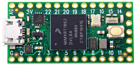
Researched this a bit more and a top contender is a Teensy 4.0 (https://www.pjrc.com/store/teensy40.html) running a Cortex-M7 at 600MHz. Unbelievably, this thing only costs $20. One per axis + peripherals isn't cheap, but it is attainable. If performance is excessive, I could conceivably run up to 3 axes through this, although I don't think that would be worth the headache.

1645213009793.png

I understand this can handle return-to-zero (RZ or "normal") serial up to 5Mbaud which meets my needs for both serial protocols. It has 7 hardware serial ports (not counting the USB interface) and is programmed through the Arduino IDE. All looking good. Signals must be 3.3V which means I'll be level shifting. Perhaps there are RS-422 transceivers which accept 3.3V logic...

Actually coding this will not be trivial, but it seems like this has the hardware needed to do it.
 
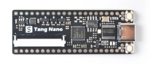
One more option. If an FPGA is better suited to this task (not sure yet) then Seeed Studios make the Tang Nano board (https://www.seeedstudio.com/Sipeed-Tang-Nano-FPGA-board-powered-by-GW1N-1-FPGA-p-4304.html). This one is $6

1645217099042.png

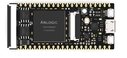
Or the Tang Primer FPGA / RISC-V. This one is more powerful and is $20

1645217199551.png

My understanding is FPGA is great at sequential logic (would have been perfect for my other robot's feedback interface boards), but not sure how it handles serial.
 
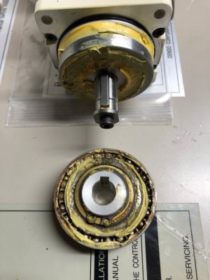
Mechanical/Controls Update: I am slowly working through opening up each joint and cleaning the gearboxes. J2 is done and I have J3 open right now. It is in better shape, but also looking somewhat starved of lubrication and some brown staining on the harmonic drive. It is less gritty than the J2 gearbox however. Eventually I'll need to grease all these joints, and I don't have the right grease, so I might as well clean them out now.

image122.jpg

Haven't heard any updates from Denso in a while. I'm trying to lay low and not bug the guy. I might check in again a week or two from now. The main info I'm waiting on is figuring out if the controller parameters can be restored now that the battery is dead. This would originally been done with a floppy disk and a floppy drive "loader" sold optionally with the robot. Without this data I think the control is pretty much dead.

Encoder / Rockwell servo drive conversion Update: Been spending a bit of time testing the waters with this idea of converting the encoder signals into something my Rockwell servos would like. Right now my "simple" task is to get a micro controller to read the serial coming out of the robot encoders and be able to store the data in memory. I'll update on that below. If that works, I want to set up the encoder channels to be read using one of the processor's built in quadrature decoder channels. If that works, I'll try to have the serial data and the encoder data in one program, and add a cross check to verify the incremental position against the absolute data in the serial, each time a new packet arrives. If that works, then I need to characterize the communications between the servo drive and a known working motor with the type of encoder I need to emulate. Then I need to program the microcontroller to be able to respond to drive requests in the same format as those motors. Finally I need to bring it all together and use the serial data from the robot to load data into memory, followed immediately by the processor using the contents of that memory to write back to the servo drive requests. Lot of work, but making incremental moves forward.

I picked up a Teensy 4.1 from my local computer supply store. This is a $20 Arduino IDE compatible board, running a Cortex-M7 processor at 600MHz - insane! I compared a lot of options and I started with this one since it has 7 serial ports, each up to 5Mbps, quadrature decoders, and hopefully enough computing power to handle all the tasks I want to do.

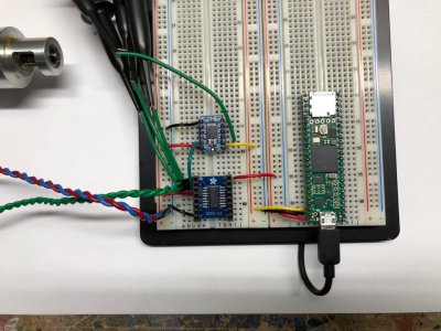
Blue board in the lower left is a breakout board for an AM26C32I RS422 differential line receiver, the one right above it is a 5V to 3.3V level shifter that actually works at 2MHz, and the big green board is the Teensy 4.1. It is only about the size of a flash drive. The Teensy 4.0 would also be a perfect fit, and is half the size (but the computer store was sold out)

image120.jpg

I am really rusty on my embedded programming so this is painful to get started on. I'm incrementally working my way towards the first task of reading the serial stream from the robot encoders. The speed of the signal (2 Mbps, or 2,000,000 bit transitions per second), the manchester encoding, and the non-standard data framing (18 data bits, 3 CRC bits, precision start and stop bits) all make this tricky. I haven't been able to find any library which supports what I want to do so I am expecting I'll have to capture the data, bit by bit using interrupts and interval timers.

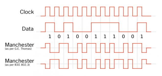
I found a super helpful white paper that talked about several processors with CLUs (Configurable Logic Units) like the PIC16F150x and how they implemented manchester decoding the the CLU before the processor gets involved. One of the tricks is that, if you can synchronize with the start bit, the logic level is equal to the voltage level 1/4 cycle before the transition point.

In the image below, the manchester data is sampled in the middle of each grid as it transitions. Transitions on the grey lines do not count. If we were to carefully time the micro to sample at exactly 25% of the way through each grid, then the measured voltage would be equal to the logic state of that bit, without needing to parse the rising/falling edge.
1645456247291.png
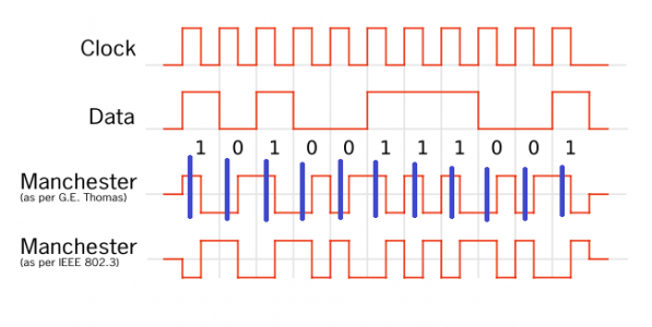
In my best MS paint skills, I've added blue ticks indicating where the processor should sample the signal. Each tick is separated by 1us. The trick will be timing the start of this sequence to align with the right spot in the data. The CRC should provide a good check against getting misaligned in the data.
1645457505768.png
Based on this, my plan for the code is:
  1. Arm rising edge interrupt (triggers a special function that interrupts everything when a digital input transitions low to high)
  2. When triggered, record time, arm falling edge interrupt
  3. When triggered, record time
  4. Calculated difference in time between interrupts
    1. If equal or greater than ~3.5us (actual start bit is 3.625us), then a start bit was found, continue to step 5
    2. If less than ~3.5us, then it was not a start bit, go back to step 1
  5. Delay small amount (couple hundred nanoseconds) as necessary to align the sampling position with 25% of each data frame
  6. Start a periodic timer @ 1us intervals. Timer triggers interrupt service routine
  7. Each timer interrupt, sample the signal, save value to memory, repeat 21 times
  8. Disable periodic timer interrupt, wait 1 us for stop bit to pass, arm rising edge interrupt (aka. return to step 1)
  9. Process data and save to memory. Do other tasks. There is a 17us delay here where nothing will happen
This code requires the processor's attention every 1us, however most of the implementation is completed in an interrupt service routine with extremely minimal processing. This should leave the processor mostly free to handle other tasks. If the processor needs to "focus" on another task like reading the serial data from the drive, or replying with a serial message to the drive, then interrupts can be turned off and the serial messages from the robot will temporarily be ignored.

Quadrature counts cannot be ignored, however, serial packets from the encoder can be ignored as much as needed. Since they repeat Ad Infinium, missing one packet will not impair the processor's ability to retrieve position data from the next packet.

So hopefully, drive communications always takes priority and an immediate response is sent, quadrature data is handled by hardware and is serviced as much as possible (no count can be missed), and the serial data from the robot is serviced whenever there is time, and we don't care is a couple packets here and there are missed.

If anyone reading has embedded programming experience and knows a better way to do this - please let me know!
 
Last edited:
My first super simple program, I am echoing the signals coming in on a digital input out onto a digital output. This is triggered by a pin change interrupt on the input pin.

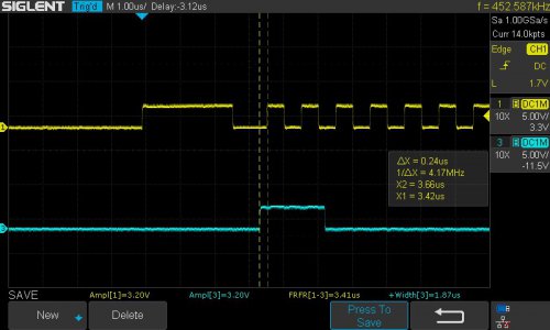
This was a success and proves a few things. First, pin change interrupts work and I can successfully catch each pulse. It also proves that there is enough processor speed to actually do something during the interrupt service routine (ISR). digitalReadFast() and digitalWriteFast() functions come with overhead to interface with the IO. These likely take up most of the processing time. In total, triggering the ISR, reading the input state, copying that data to the output pin, and writing that value to an actual voltage took about 120ns or 72 clock cycles. This is pretty good. In reality, I won't be doing the digital write, which should save some time. If I could set up both rising and falling edge interrupts (not sure if possible) then there also would be no need for a digital read either.

EDIT: With dual interrupt service routines (RISING and FALLING) I was able to eliminate the digitalReadFast() and get the skew down to 100ns or 60 clock cycles. I think this is about as good as it gets without DMA.

EDIT: Direct Memory Addressing (DMA) is another option to improve speed. This is way outside my wheelhouse, but my understanding is that the IO ports are set to slow mode when making the pins available to the processor for read/write. The IO port can be placed in fast mode for DMA, which could reduce latency. But then the pins can only be handled by DMA. I don't know if these timing interrupts can be accomplished with DMA.

My timing goal is to synchronize within 250ns, so I think the capability is there.

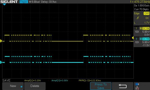
In the image below. Yellow is the signal from the encoder, blue is the signal echoed by the micro. The 3rd measurement (FRFR[1-3]) is the skew between the first rising edge of each of the channels, or the delay in processing the signal.

image124.jpg

C++:
#include <avr/io.h>
#include <avr/interrupt.h>

/* This code takes a high speed input on pin 15 and echos it on pin 13
* This was to try to recreate the manchester encoded serial data @ 2Mbps
* This code is successful with a skew of ~120ns or 72 clock cycles
* Most of this time is likely digitalReadFast() and digitalWriteFast()
* Time is not affected by choosing other pins
*/

int PinInt1 = 15;
int PinOut1 = 13;

void setup() {
  // put your setup code here, to run once:
  pinMode(PinInt1, INPUT); // sets the digital pin as output
  pinMode(PinOut1, OUTPUT); // sets the digital pin as output
  Serial.begin(115200); //Start USB logging to computer
  attachInterrupt(digitalPinToInterrupt(PinInt1), isrService, CHANGE);
}

void loop() {
  // put your main code here, to run repeatedly:
  delay(1000);
  Serial.println("Running");
}

void isrService()
{
  digitalWriteFast(PinOut1, digitalReadFast(PinInt1));
}
 
Last edited:
Got another test program written.

This one expands on the lessons learned on the previous piece of code and focuses on properly identifying the start bit of the serial burst. To do this, I enabled a register which counts the 600MHz clock cycles in a 32 bit memory address. This overflows every 7.16 seconds so care needs to be taken to handle the overflow case.

I trigger an interrupt on the rising edge and grab the cycle counter value. I then disarm the rising edge interrupt and arm the falling edge interrupt. When the pulse falls, I grab the cycle counter again, save it in another variable, and disable the falling edge interrupt. A flag is set indicating that a pulse has been measured.

In the non-interrupt code, once the flag is set, the cycle count at the rising edge is subtracted from the cycle count at the falling edge. If the falling edge count is less than the rising edge count, then the counter rolled over and we need to do (cycleCountFalling + 2^32) - cycleCountRising. The "LL" after the 2^32 constant forces the processor to perform the intermediate math on a 64 bit wide memory address to avoid truncation. The result is checked. If too short or too long (shouldn't happen) then we know the pulse measured wasn't the start pulse. We clear the flag and re-arm the rising edge interrupt to catch the next pulse.

If the pulse width falls in the range of a start pulse, we begin our packet sequence. Right now, all this does is delay a precise value to align a diagnostic output pulse on the desired measurement location (250ns prior to the next rising pulse). Eventually this will start a periodic interrupt timer which reads the data starting at 250ns prior to the next manchester transition, then exactly 1us thereafter for a total of 21 reads. Having a bit of trouble with this periodic interrupt at the moment.

There is a bit of time to be saved by checking the port interrupt flag rather than just the pin change. Many pins share one port interrupt, so if a pin interrupt is enabled, then at the time of the interrupt, the processor must take time to figure out which pin triggered the interrupt. If I am only using one pin per port, then this extra check is not needed.

image127.jpg

C++:
#include <avr/io.h>
#include <avr/interrupt.h>

int PinInt1 = 15;
int PinOut1 = 13;
volatile unsigned int clockCyclesRising = 0;
volatile unsigned int clockCyclesFalling = 0;
unsigned int clockCyclesElapsed = 0;
volatile bool intFlag = 0;
IntervalTimer myTimer;

void setup() {
  pinMode(PinInt1, INPUT);
  pinMode(PinOut1, OUTPUT);
  attachInterrupt(digitalPinToInterrupt(PinInt1), isrServiceRising, RISING);
  ARM_DEMCR |= ARM_DEMCR_TRCENA;  //Might not be needed for Teensy 4.x
  ARM_DWT_CTRL |= ARM_DWT_CTRL_CYCCNTENA;   //Might not be needed for Teensy 4.x
  Serial.begin(115200);
}

void loop() {
    if (intFlag == 1){
      if (clockCyclesFalling > clockCyclesRising)
      {
          clockCyclesElapsed = clockCyclesFalling - clockCyclesRising;
          
      }
      else //Handle the case where rollover occurrs between the samples. (2^32)LL forces 64 bit intermediate computation
      {
          clockCyclesElapsed = (clockCyclesFalling + 4294967296LL) - clockCyclesRising;
      }
      if ((clockCyclesElapsed <= 1570) || (clockCyclesElapsed >= 1590)) //Pulse too short (<2us) or too long (>4.5us)
      {
          intFlag = 0;
          attachInterrupt(digitalPinToInterrupt(PinInt1), isrServiceRising, RISING);
      }
      else //Pulse is a start bit (2us<x<4.5us) . Exact clock counts should be narrowed
      {
          intFlag = 0;
          //Serial.println(clockCyclesElapsed);
          delayNanoseconds(450);
          digitalWriteFast(PinOut1, 1);
          //delayMicroseconds(5);
          //digitalWriteFast(PinOut1, 0);
          myTimer.begin(isrPeriodic, 0.8);  //Does not trigger below 0.8us
          //Do periodic timer stuff here
      }
    }
}

void isrServiceRising()
{
  intFlag = 0; //in case the pulse measuring code in loop hasn't been serviced by the time the next interrupt occurs, clear the flag bit
  clockCyclesRising = ARM_DWT_CYCCNT;
  attachInterrupt(digitalPinToInterrupt(PinInt1), isrServiceFalling, FALLING);
}

void isrServiceFalling()
{
  clockCyclesFalling = ARM_DWT_CYCCNT;
  intFlag = 1;
  detachInterrupt(digitalPinToInterrupt(PinInt1));
}

void isrPeriodic()
{
digitalWriteFast(PinOut1, 0);
myTimer.end();
attachInterrupt(digitalPinToInterrupt(PinInt1), isrServiceRising, RISING);
}
 
Hi,
Your project is super impressive. I was just wondering if the encoders of the other joints on your robot are daisy chained to a serial bus between the arm base and controller?
 
Hi,
Your project is super impressive. I was just wondering if the encoders of the other joints on your robot are daisy chained to a serial bus between the arm base and controller
Hi Bender,

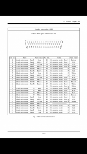
From what I can tell, the serial channels are entirely in parallel. Each motor/encoder gets its own channel back to the main controller.
Pinout from the maintenance manual. There are 6 instances of “motor encoder phase Rx”.

052FFCEB-2C76-415A-B3B7-95A883847CB1.png

plus, at the baud rate of the serial channel, there isn’t enough dead time on the wire for even two encoders to share without interfering with eachother
 
Thanks. On the newer, but still old and obsolete, rc5 controller they seemed to have changed to daisy chaining them together with what I assume to be rs485. The seem to be using some propriety panasonic encoder protocol too. Keep up the good work on your project!
 
Thanks. On the newer, but still old and obsolete, rc5 controller they seemed to have changed to daisy chaining them together with what I assume to be rs485. The seem to be using some propriety panasonic encoder protocol too. Keep up the good work on your project!
Huh cool! Thanks for sharing that. I have no experience with any Denso robots with the exception for the one I am messing around with right now. The motors I have are addressable (although not sure how address setting would even be achieved) but limited to 0-3, so not enough addresses for the whole robot.

The interesting this is that Denso special ordered these Panasonic motors with non-standard encoders. Kinda strange.
 
Back
Top