My next CNC project - a CNC router

My original concern wasn't the slope, but the lack of support, continuity, reliability and longevity typical of buying board #2 of 10 (BETA).
It's funny you mention Beta as the fellow that was helping me this week said that my issues were part and parcel of being part of a beta group. That was the first I'd really thought about the fact that this was pretty bleeding edge stuff and likely not the right path for me.
 
Last edited:
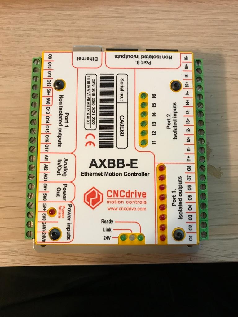
My new controller arrived today!
0f628b511e7730468d595a56af21101b.jpg
 
Time to start filling up the enclosure.
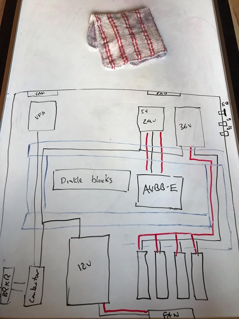
Here is a rudimentary (emphasis on rudimentary!) sketch of how it's going to come together.
dc68de4961b99ab6d385d601c821b580.jpg


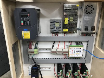
From the top left VFD, 5v/24v power supply for the controller and limit switches, 36v power supply for the stepper drivers,
Middle is a row of Dinkle terminal blocks for power distribution and the AXBB-E controller.
Bottom left are 120v breaker, contactor, 12v power supply for the three fans, and the four stepper drivers.
In the top right on the outside are the e-stop, and on/off switches. There may also be a potentiometer for VFD speed control. We shall see how controlling the YLang VFD via PWM turns out.
 
Last edited:
Time to start filling up the enclosure.
Here is a rudimentary (emphasis on rudimentary!) sketch of how it's going to come together.
dc68de4961b99ab6d385d601c821b580.jpg


From the top left VFD, 5v/24v power supply for the controller and limit switches, 36v power supply for the stepper drivers,
Middle is a row of Dinkle terminal blocks for power distribution and the AXBB-E controller.
Bottom left are 120v breaker, contactor, 12v power supply for the three fans, and the four stepper drivers.
In the top right on the outside are the e-stop, and on/off switches. There may also be a potentiometer for VFD speed control. We shall see how controlling the YLang VFD via PWM turns out.
Keep the VFD and its output cables in the lower corner. Helps with cooling and you want those noisy cables as far from everything as you can get.
 
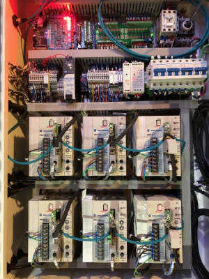
Here's a panel I built. VFDs and servo drives generate significant electrical noise that can cause issues with your low voltage control circuits. They need to be separated as much as is reasonably possible, and good grounding, bonding, and shielding are a must. Read your drive user manual and application documents to see good grounding and bonding practices.

Sensitive low voltage control boards are at the top, higher voltage AC drives (big white boxes) are at the bottom. Motor output cables are routed in wire ducts away from any signal cables and they cross at right angles where necessary. Drives are electrically grounded, as well as bonded to the unpainted subpanel.

Still had a bit of EMI issues which were resolved with EMI ferrite toroids, shielded cables inside the cabinet, and scraping paint off the back of one of the drives to improve bonding to the subpanel.

1645714763768.png
 
Keep the VFD and its output cables in the lower corner. Helps with cooling and you want those noisy cables as far from everything as you can get.

Thanks John,
My intention was to have the spindle cable leave the enclosure right below the VFD so that there’s minimal spindle cable inside the enclosure. I have also put a fan directly above the VFD for cooling.
Does that sound like a reasonable approach?


Sent from my iPhone using Tapatalk
 
Last edited:
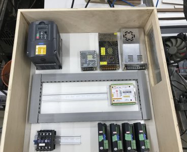
Massive progress today. At 10:30 this morning I had the electronics laid out as below.
Enclosure_layout.jpg

At 3 PM I had all the DC and the AC wiring done except for the breaker, contactor, on/off and emergency stop switches wired in.
enclosure_wired.jpg
Shortly after 3pm I had movement on all three axes!

Very happy with how the wiring turned out. Super impressed with the UCCNC software.

Just have to drill the bottom left panel for cable glands for power, stepper cables and limit switches. Top right panel will get emergency stop and on/off switches.
 
Another big step tonight.
I was struggling with getting the limit switches set up. Wiring was right but they weren't working as expected.
A bit of research revealed some user error in the configuration. A couple of changes in the software config and now all axis have working limit switches and the homing cycle works!
I'm about a hair's breadth away from cutting :p
 
Last edited:
So a thing happened.
Nothing amazing. But I had to see if everything worked.
No magic smoke from the spindle or VFD
Coolant pump worked.
No broken endmill from crashing into anything.
But I had my hand on the software e-stop the whole time.:eek::eek::eek:
Despite how much I've learned I now know how little I know and how much more I have to learn.
Still to do:
- Wire in contactor, physical e-stop, on/off buttons.
- Drill a boatload of holes in the enclosure for cable glands
- Install enclosure cooling fans (arriving Thursday)
- Route limit switch wiring in enclosure
- Route stepper cables in enclosure
- Finish spoil board attachment
First_cut.jpg
 
Last edited:
Back
Top